Oldham Optical usually coats its mirrors with Aluminium as the reflective layer over-coated with a protective layer of Silica 1/2λ thick. This arrangement is usually known as “Protected Aluminium”. We believe this combination is the best compromise for general purpose astronomical mirrors. There are other coatings that can be used. This page is intended to give some details of the different coatings with the underlying principles behind them and the manufacturing process.
Metallic Reflectors.
Possible metallic reflectors for astronomical mirrors include Aluminium (Al), Silver (Ag) and Gold (Au). The relative performance of each material across the visible spectrum is shown in the adjacent diagram.
It can be seen that Gold is a poor reflector for astronomical purposes as its reflectivity drops off sharply towards the blue end of the spectrum, but if you were designing an infra red telescope, it would be the best of the three metals to have.
Silver is a fairly good reflector over the whole visible band and is better than Aluminium at wavelengths longer than 500nm. It does tarnish quickly if the surface is unprotected and this rapidly reduces the reflectivity. It can be given an overcoat of Silica (Silicon Dioxide), which does slow but not completely stop tarnishing. The remaining big drawback with Silver is that it is a lot more expensive than aluminium.
Aluminium has good general performance as a reflector over the visible spectrum and it is very cheap compared to the others. Considering how many Aluminium products you will have in the home, it may surprise you that bare Aluminium rapidly oxidises on contact with air. But the Aluminium Oxide coating formed is transparent and nearly impervious after a short depth has formed. The oxide layer will slowly thicken over time but the mirror is generally usable for over a year before the declining reflectivity requires it to be re-coated.
On balance, comparing costs and performance of Aluminium against Silver and Gold, it is generally accepted that Aluminium is the best choice for general purpose astronomical use.
The optimum thickness of Aluminium is in the range 75-100nm. This is the compromise area where the thickness is sufficient to cover the glass and avoid leaving partial transparency, yet not thick enough for the coating process used to develop significant unevenness in the layer.
A general rule is that the thickness of the reflecting layer should not vary by more than 1/100λ else it will affect optical performance. The normal coating process (described later) is aimed at maintaining thickness within 5%. So a thickness of 100nm is about the limit that would cause 5nm or 1/100λ unevenness.
Bare Aluminium is extremely fragile. It is easily marked and scratched. This does not stop bare Aluminium mirrors being used in large observatories. They prefer the bare surface because of the flatter reflectivity response across the full infra red to ultra violet spectrum. Observatories usually have their own vacuum chamber for easy re-coating at between 12 and 24 month intervals.
Most users who do not have such ready access to a coating chamber prefer that the bare Aluminium is given an overcoat to protect the surface to delay oxidation and protect the surface from scratching. The most common coating used for the visible spectrum is “Silica”. Chemically this is Silicon Dioxide (SiO2). Another fairly common coating is Magnesium Fluoride (MgF2), which is better for the ultra violet part of the spectrum.
Any overcoat does reduce the reflectivity but makes an Aluminium mirror usable for say over 10 years without re-coating. In the case of the Silica overcoat it can either be applied extremely thinly just sufficient to seal the Aluminium away from the air – in which case the mirror reflectivity is about 4% lower than that of bare Aluminium throughout the spectrum. More usually the coating is applied to a depth equivalent to 1/2λ in the middle of the visible spectrum. Using Silica as the overcoat, then after taking the value of refractive index (1.46), into account, this works out to be a thickness of about 190nm. The effect of this particular thickness is to boost reflectivity in the middle of the visible band nearly back to the bare Aluminium value, but it does tail off at each end of the visible spectrum.
An Aluminium mirror over coated as above is known as “Protected Aluminium”.
Usually the overcoat of silica or MgF on a “Protected Aluminium” mirror is 1/2λ, – but check the thickness if it is not made clear. It may mean the very thin coating just sufficient to seal the Aluminium in.
Dielectric Reflectors.
Instead of one good reflecting layer, a mirror can be produced using a stack of partial reflecting layers in series. The materials used are usually referred to as “Dielectric” materials and the resulting mirror is known as a “Dielectric” Mirror.
The principle is that when light attempts to travel from one medium to another, a portion of the light is reflected. If a stack of alternating layers are laid down on top of each other then the arrangement produces a number of reflective layers in series one behind the other.
Each reflects a percentage of the light reaching it. This makes the multilayer combination into an extremely good reflector. Usually two materials with sharp differences in their refractive index are used and the thickness of each layer is related to 1/4λ thick. This thickness causes the reflections from all the layers to re-combine in phase.
Lots of different materials can be used for the layers. Many metal oxides can be used as well as many metallic fluorides and Sulphides. Two materials often used are Zinc Sulphide (ZnS), and Magnesium Fluoride (MgF), with refractive indexes of 2.32 and 1.38 respectively.
Both layers are usually arranged to be 1/4λ thick to light.
The different refractive indexes means the Zinc Sulphide layers are physically thinner than the Magnesium Fluoride layers in proportion to the inverse of their refractive index value.
While these coatings can be designed to give reflectivity’s greater than 99.9% over a very narrow range of wavelengths they cannot offer a broad response across the visible spectrum. If a reflector for a single frequency laser is required, then a dielectric mirror will often be the best solution, – but this sort of reflector is not practical as a general purpose astronomical mirror across the visible spectrum.
However it is possible to overcoat a metallic reflecting layer, – usually Aluminium – with a small number of dielectric layers and using this principle “enhance” the performance of the aluminium. This is what is generally termed an “Enhanced Aluminium” mirror. Perhaps 2-6 dielectric layers are involved on top of the Aluminium.
While the dielectric mirror example given suggests two materials are used with thicknesses directly related to 1/4λ thick. More than two materials may be used and its not necessary to stick with thicknesses directly related to 1/4λ, – although the effective difference between the different material layers must still end up being 1/4λ different for the process to work. The specific materials and thicknesses used in the dielectric layers are usually proprietary to the coating manufacturers.
If you are considering an enhanced aluminium mirror, then clarify with the supplier what materials are being used. It will be useful to know this when the mirror coating comes to the end of its useful life and it is necessary to strip off the coatings. Some materials are more difficult to remove and result in the mirror figure being damaged..
The (maximum) improvement claimed for enhanced over protect Aluminum is about 5%. An example performance graph of Enhanced verses protected Aluminium and with bare Aluminium as a reference is adjacent. We suggest this 5% may apply for 4-6 layer systems and a reduced number of layers give less
We are aware that one “enhanced Aluminium” mirror recipe is only one extra layer. It comprises the standard “protected” Aluminium coating of 0.5λ Silicon Dioxide followed by a single layer 0.25λ thick of Tantalum Pentoxide. While we have not seen any performance figures for this recipe, we do not expect it to perform as well as 4-6 layers, but it is still marketed as “enhanced”. It will certainly give some improvement, but perhaps not as great as 5%? However as it is only one extra layer it should be cheap to apply.
A Cassegrain telescope involves two mirrors. So the extra light delivered to the focus will be about 10% greater where two enhanced Aluminium mirrors are used compared to protected Aluminium.
A Newtonian also has two mirrors, the Primary and the elliptical flat. Be aware that the same coating as used on the primary will not work on the elliptical flat which is operated at 45 degrees. Flats require different thicknesses of each layer to account for the 45 degree angle of incidence. Even then there may be problems from partial polarisation due to the angle. If the partial polarisation reduces the light reflected by 5%, – you have wasted your money paying for an enhanced aluminium coating! Protected Aluminium does not present the same level of problem.
Coating Methods
Apart from depositing a layer of Silver, which can be deposited chemically, most coating involves a vacuum chamber. A very high vacuum is required and there are usually two pumps involved. The first is a rotary vane pump or similar type that removes the bulk of the air from the chamber sufficient for a traditional oil diffusion pump to be brought into circuit between the chamber and the rotary pump to go on and produce the extremely high vacuum required. The diffusion pump may be replaced in more modern systems with a very high speed turbine pump that can achieve matching or even higher vacuums.
The main method used in the coating process is to directly heat the coating material to a high temperature in the vacuum and evaporate it. A tungsten heating element in close proximity heats the coating material.
If it is Aluminium being used as the coating, it is common to directly wrap Aluminium wire round the Tungsten heater element.
Because of the low pressure, the coating material changes directly from its solid form to a gas with no intermediate liquid phase. The gas then condenses on any cooler objects nearby which will include the mirror.
After coating with say Aluminium then if an overcoat is needed, a second heat source nearby loaded with the coating material is switched on and evaporates the coating in the same manner. If a series of layers for a dielectric coating are to be applied, each may have its own heater which will operate in turn.
The “traditional” vacuum chamber used for coating suspends the mirror over the heater with the distance between the mirror and the heater equal to the radius of curvature of the mirror. Since the heated material evaporates evenly in all directions, this geometry automatically results in a very even thickness of the coating over the full mirror surface. There is no risk of the mirror figure altering due to a varying thickness between centre and edge of the mirror.
However for a lot of big mirrors, this would need an enormous vacuum chamber! Common modifications are to change the geometry of the vacuum chamber to use a series of heaters across the full area of the mirror. Another chamber design maintains a single heater but sites it towards one side of the chamber while rotating the mirror during the coating process. This allows the rotation to even out the coating.
Each technique is aimed at evening out the coating delivered to the mirror surface with the aim to keep the coating thickness within 5%. If the deposited Aluminium layer was 100nm thick, the unevenness would work out to be about 5nm which is about 1/100λ and is small enough not to worry about.
Oldham Optical have often tested examples of mirrors before and after coating. We have never detected any measurable difference in the mirror figure before and after. So our experience is that unevenness is not a problem.
Modifications on the basic process.
The principle behind all methods is to separate individual atoms of the coating material and deposit them in a controlled manner as an even layer on the surface of the mirror.
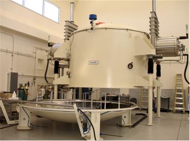
For very large mirrors, where the problems of raising the mirror in the chamber are excessive, the mirror is located at the bottom of the chamber and the heater elements arranged at the top. the only disadvantage of this is that any dust in the chamber or any loose material will end up on the mirror surface. The picture adjacent is the vacuum chamber at the Air Force Research Laboratory’s Starfire Optical Range at Kirtland Air Force Base. It is capable of Aluminising a 3.5m mirror.
Instead of a tungsten element, an electron gun can be used to heat the coating material. This allows materials to be used with melting points above that of Tungsten. The electron beam can easily be deflected into adjacent crucibles to apply the overcoats.
After the vacuum in the chamber is established but before coating starts, there may be some preliminary processes. Although the mirror surface will have been well cleaned before being put in the chamber, an electrical discharge is often passed through the chamber first. This excites remaining residual atoms in the chamber. The atoms speed up and bounce round the chamber. They have the effect of sandblasting the inside of the chamber surface and the mirror. This gives it a final clean.
The evaporation process of some materials can be spoiled by atoms of oxygen and other atmospheric gasses that have adhered to the sides of the chamber and have managed to resist the initial vacuum. Most of the unwanted gasses can be released before coating starts by heating the chamber. Conversely during the coating phase, some dielectric materials actually prefer that a small amount of Oxygen is deliberately introduced during the coating process. This helps adhesion of the coating for these materials. Sometimes ionisation is maintained within the chamber which helps the coating atoms pack correctly on the surface.
An alternate technique to evaporation is called “Sputtering”. This method operates at a lower vacuum. Trace gasses are deliberately introduced to the chamber. These trace gasses are energised by an electric arc from electrodes sited close to the coating material, or by radio frequency energy from a small aerial.
The arc or the radio signal energise the trace gasses to move at extremely high speed within the chamber. They bounce off the walls and the nearby coating material. On striking the coating material they break off individual atoms. These loose coating atoms eventually deposit themselves on the mirror in an even layer.
Finally, some chambers may be arranged where instead of the mirror lying horizontally, it is turned through 90 degrees and hangs vertically.
Enhanced Aluminium v Protected Aluminium.
While an enhanced Aluminium mirror will reflect up to 5% more light, there are factors in the manufacturing process that are more critical than for the simpler protected Aluminium mirror. Oldham Optical believe they are significant. The more complex process and different materials may mean the enhanced mirror has a shorter life before it needs recoating. And when it does need re-coating, its more likely to need re-figuring as well.
For the protected Aluminium mirror, the thickness of the aluminium coating is not critical. It is a reflecting layer. It is only necessary to deposit sufficient Aluminium to ensure a full cover. Any value in the 75-100nm band gives sufficient cover without causing excessive roughness of the surface.
If it is a simple chamber as described above, with the mirror at roughly its radius of curvature from the heater then the simplest way to work out what thickness of Aluminium will be achieved on the mirror is to assume the Aluminium when heated will vaporise in every direction evenly as an expanding sphere. Calculate the ratio of the area of the mirror to the area of the sphere that has the same radius as the gap between mirror and heater. From this ratio work out the weight or volume of Aluminium that must be put into the chamber to give say an 85nm thickness.
Neither is a Silica overcoat thickness particularly critical. It is aimed at being 190nm thick, but errors just move the peak response slightly up or down the spectrum. So production of a “protected Aluminium” mirror is not very critical.
By comparison the thicknesses of the dielectric layers used in the enhanced mirror must have very tight tolerances to get the improved performance. There are a greater number of layers to lay down. For these more critical layers the vacuum chamber may need fitting with equipment that continually measures the reflectance of the surface as the thickness of a layer builds up. When a peak in reflection is noted, the process can be stopped and move on to the next layer.
An alternate testing method is that once the coating is finished the mirror is removed and subjected to tests of its reflectivity. It will be rejected if it does not met the standard set. However since astronomical mirrors are usually large and will not easily fit in the sort of machines commonly available for testing reflectivity, small samples placed inside the chamber with the mirror may be tested instead of the mirror itself. They should have received the same coating thicknesses.
If a mirror with dielectric layers has to be rejected, it may be a major set-back. Depending on the dielectric materials used, the coating may not be removable without damaging the mirrors figure. The mirror may end up being sent back for re-figuring and testing before the next attempt to re-coat. If you are obtaining an enhanced Aluminium mirror then you are advised to find out what materials are being applied. So you will be aware of the consequences and costs when it subsequently has to be re-coated.
Even when the layers are laid down to the correct thickness, the dielectric mirror will on average have a shorter life. The evaporation process leaves stresses in the thin materials. The different coefficients of thermal expansion of the materials cause more stresses between the layers from temperature changes during its life. While Aluminium has a coefficient of thermal expansion that is considerably different from glass, it sticks extremely well to glass and successfully withstands the normal tensile and compressive stresses of its daily life fairly well without cracking or delaminating. Silica and Magnesium Fluoride when used as single overcoats have similar characteristics.
Some other materials used in the dielectric layers are not as good in this respect. They do not resist equivalent stresses as well. Exceeding the material tensile stress limit causes a series of tiny cracks to appear over the mirror surface. This is known as “crazing”. Exceeding the compressive stress limit causes flakes of one layer to delaminate. Increasing the number of layers increases the chance of a stress problem appearing within a certain time. While coaters strive to improve their technique, It is suggested that an Enhanced Aluminium mirror, (with more layers), is likely to need re-coating more often than a protected Aluminium mirror.
Removing The Old Mirror Coating
After say ten years or more a Protected Aluminium mirror will need re-coating. But first the old coating must be removed. Along with most other mirror makers, we use a chemical system to remove the old coating. In our case we normally use a combination of Hydrochloric acid with Copper Sulphate.
It only takes the chemical a few minutes to remove the coating and we wash all the chemical off as soon as all Aluminium has been removed. When you consider that for a Protected Aluminium mirror the acid has first had to eat through 190nM of Silica and then 85nM of Aluminium, – then not expecting the acid to carry on and eat away at the glass surface of the mirror underneath the aluminium is perhaps being naive?
If your mirror is 0.1λ “as measured at the focus” then it only takes an error of 25nM on the surface to take it out of tolerance. 25nM is a lot smaller than either the thickness of the Aluminium (85nM), or of the silica overcoat (190nM). If for instance there is some contamination that prevents the Silica and Aluminium being removed very evenly, then some parts of the mirror will become clear of aluminium well before the rest and the acid solution will continue and remove part of the mirror itself.
Remember that plate glass, or any low expansion glass, or virtually any other sort of glass used for mirrors can be described as “Silica with various impurities added”, and you can see that if the acid solution can remove a pure silica overcoat, it can also attack the surface of your mirror.
So the figure of the mirror can be affected before all Aluminium is finally removed. We do wash off the acid as soon as we can see the Aluminium has been dissolved and we seem to get away without needing to re-figure most of the time, – but it can’t be guaranteed. If there are extra layers, and more exotic materials are employed which are more difficult to remove, then its increasing the chance that re-figuring the mirror will be necessary after the coating has been removed.
Perhaps here is one reason large observatories prefer bare Aluminium? If the acid does not have 190nM of Silica to eat through first to get to the Aluminium, the Aluminium layer itself will be more evenly removed. This would minimise any effects to the underlying mirror surface.
Overall Performance Of Enhanced Over Protected Aluminium
(Or is the 5% extra light worth it?)
The mirror will be used either for direct viewing or for Astrophotography:
To make one stop difference in exposure time for Astrophotography, the difference would need to be about 50% rather than the 10% provided by a pair of mirrors. Oldham Optical suggest the improvement is hardly noticeable in practice. For direct viewing, then the light difference will hardly be noticeable to the naked eye either.
The enhanced Aluminium mirror costs more than protected Aluminium because of the greater number of layers and the increased precision necessary in the coating process. It will give up to 5% more light per mirror as a result.
But the Enhanced Aluminium coating has more layers. On balance, because of the increased number of layers the odds are that the enhanced coating will deteriorate a bit faster than the simpler protected Aluminium coating. When it comes to the end of its useful life and needs re-coating, then because of the increased difficulty in removing the coating, the enhanced mirror is more likely to need re-figuring.
Other factors affecting the life of the mirror are environmental. If you can keep it in a dry atmosphere, it will last longer, If you are lucky enough to live in an area of low air pollution, it will last longer. And if you can minimise temperature changes to avoid stress in the layers, – perhaps especially important for enhanced Aluminium mirrors, but also good for protected Aluminium, – it will also last longer.
If you really want more light to the eye, then perhaps the best way is a slightly bigger telescope with a larger primary mirror. Changing a 300mm diameter mirror for one of 325mm would give 20% extra light for example.
You may also get an improvement by changing your eyepiece? Choose a design that contains less glass elements. A glass air interface without an anti reflection coating loses 4% light. This does reduce to about 1% with a good anti reflection coating. But where you have a large number of separate glass elements within the eyepiece, the total losses could be over 10%.
Oldham Optical suggest that on balance the protected Aluminium mirror is the most cost effective for the amateur astronomer and that is what we supply. But if customers want an enhanced Aluminium mirror, Oldham Optical can supply a clean uncoated mirror for a third party to coat.
If you are considering an enhanced Aluminium mirror, then you should ask for full details of the enhanced coating. Ideally you will be supplied with a list showing each layer material and thickness. You should also ask for the expected life of the mirror before it needs re-coating. Plus the chances that the mirror will require re-figuring at the next re-coating.
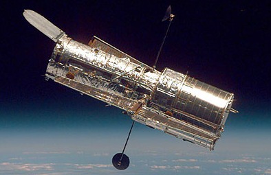
And Finally – What Do You Think The Hubble Uses?
The Hubble mirrors are coated with Aluminium 100nm thick with a protective layer of Magnesium Fluoride 25nm thick. The use of MgF instead of Silica and at this thickness is to optimise performance in the ultra violet region.
Oldham Optical suggest the Hubble provides very good support for the use of protected Aluminium mirrors by terrestrial astronomers.