Interferometers And “Conventional Testing” Of Mirrors
We are often asked if testing with Interferometers is better than a conventional Null test. The answer is a resounding “No” For high accuracy in astronomical optics, Interferometers cannot compete with the Time Honoured method of a knife edge and the human eye in a Double Pass Null test. If they could, we would be using an Interferometer instead of conventional methods.
“Conventional Methods” – The Double Pass Null Test
What follows is a description of the Double Pass Null Test as carried out at Oldham Optical. This is the basic test we use on all large parabolic mirrors. The description is very simplified and is aimed at peak to valley (PV) measurement, but all the Double Pass strengths are brought out to illustrate why it is such a good test of a mirror. This test is also known as “Auto-collimation” and most professional mirror makers agree with us that it is the definitive bench test of a parabolic mirror.
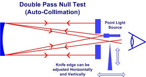
The diagram adjacent shows the basic arrangement of a parabolic mirror set up under test conditions facing an optical flat that has a central hole. A point light source is set up near the focal point of the mirror and shines through the central hole onto the surface of the parabolic mirror. The light reflects back (parallel to the axis of the system) to the optical flat which reflects it back along the same path to the parabolic mirror again.
It reflects off the parabolic mirror a second time and returns to a focus near the original light source. In practice the light source has to be set up just slightly off axis so the focus of the reflected light can be accessed, or use a beam splitter to maintain axial symmetry. A knife edge is set up at the exact point of focus.
The knife has micrometer adjustments to allow it to be adjusted slowly and accurately into the returning light cone. The detector used in the Double Pass Null test is of course the “Mk1 Eyeball”. In our case the person wielding the eyeball has developed the skill from carrying out the test a great number of times. Whilst an amateur setting up this test for the first time would certainly benefit from being led through the test by a more experienced person, – once they has been led through the test once, – they would probably be able to repeat it on their own.
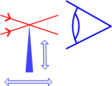
The next diagram is an enlargement of the light rays passing the knife edge. If the mirror is the perfect parabolic shape then all the rays of light will come together at the focal point. If the knife edge is moved on its micrometers it will be possible to find a single position at which all the light rays are cut off by the smallest vertical movement. The observer would see an instantaneous Null, (total blocking of all light), as the knife edge is moved into the beam (vertical movement as shown on the diagram.)
In practice, it is not possible to make an absolutely perfect mirror, although some of us can get fairly close! When the parabolic surface is not absolutely perfect the light rays coming back will not pass through one fixed point. They will range around the nominal focal point.
In this next diagram the range is shown by the solid and dotted lines. Say in this next example that light rays from the centre of the mirror are represented by the solid lines and rays from the edge of the mirror are represented by the dotted lines. Everywhere else focuses somewhere in between. If the knife edge is adjusted to the same point as in the first diagram, then only part of the mirror (the centre), will be Nulled. There will be a dark centre on the mirror where it is Nulled and the image on the outer areas of the surface will be dark and the other side will be light. Once at this position, horizontal movement of the knife edge will make the dark centre expand out to a ring and continue to expand out across the surface of the mirror. The ring will reach the edge of the mirror when the knife edge is in the dotted position shown corresponding to the rays from the edge of the mirror. The horizontal movement of the knife edge needed to move from the Null at the centre to the Null at the edge is a direct measure of the surface error on the mirror. So once the test is set up and adjusted, only one movement of the micrometer, noting two positions, is needed to take the test results, this is complemented with a high power eyepiece.
There are plenty of texts giving the Mathematical relationship between the horizontal movement and surface error and we are not going to explain them in detail here. Using a 20″ F/4 Mirror as an example, the horizontal movement equating to PV 1/10λ error on the Wavefront is 0.11mm or 0.0044″. For a PV 1/4λ Wavefront error, the figures are about 0.28mm or 0.011″.
Therefore apart from a simple multiplication, the Double Pass Null Test directly measures the error on the surface (or on the Wavefront of course!) Figures as low as 0.11mm might at first seem small and difficult to measure, but that is exactly why the knife edge is equipped with a micrometer movement that can measure horizontal distance to an accuracy of better than 0.01mm.
of the Double Pass Null test is in the name itself. Light reflects off the mirror twice, so that errors are doubled compared to testing on the sky.
The strengths of the Double Pass Null test are as follows:-
- Double Pass shows Double the error.
- Test Results obtained from one simple micrometer movement.
- Measures error directly – No derived figures.
- Can always measure to better than 1/30λ.
- Only a Good Optical Flat needed, – Rest of equipment can be “cheap and cheerful”
- Easy Way To Check the Optical Flat by repeating test with Optical Flat moved or turned on axis.
- Only accurate alignment of Mirror and Optical Flat needed.
Testing Us
Mechanically the set-up can theoretically measure PV Wavefront on our 20″ mirror to an accuracy better than 1/100λ. However it is not quite as good as that because the exact position at which the Null reaches the edge of the mirror is partly subjective. Some figure better than 1/30λ is readily achievable. An advantage is that the testing method involves only one movement of the micrometer.
So What Could Go Wrong With The Double Pass Null Test?
About the only thing that can is a problem with the optical flat. Ours are better than PV 1/20λ and are all tested by external Optical Engineers. If any problems are suspected with an optical flat then the problem may be in the optical flat support. – the optical flat can be rotated on its axis (say 45 degrees), and the test done again. Any difference between the test results would suggest a problem with the optical flat support.
The Double Pass Null test therefore has an easy method of checking for problems with the only part that matters, – the optical flat. Setting up a Double Pass Null Test involves only one accurate alignment. This is to line up the Optical flat at exactly 90 degrees to the mirror axis. This does entail both horizontal and vertical angle and generally takes about 15 minutes to set-up a new mirror the first time it comes off the polishing machine. Subsequently it only takes about 1 minute once the settings are known. Finding the exact focus of the converging beam with the knife edge is easy and intuitive. The micrometer movement controlling the knife edge enables it to be found and set to better than 0.01mm in typically less than a minute. After this quick set-up, the remaining error on the mirror surface can be read off.
One of the strengths in An Interferometer
An Interferometer can be built from scratch, but they may be proprietary devices bought from a specialist company. “Zygo” is a very well known and respected brand name but there are others. Interferometers use two main techniques to measure errors on mirrors. The technique most often used for Astronomical mirrors is called “Fringe Analysis”. In this method an Interferometer is set up to generate fringes between the object under test and a reference object.
The fringes are then compared with an ideal set of fringes generated by a computer. Any difference between the two sets should indicate an error in the mirror under test but at times the error is in the Interferometer setup! The method will be covered in detail later, – but first a brief description of the other technique, with a caveat that it is not often used.
This second technique is called “Phase Shifting Interferometry” It requires a more expensive Interferometer capable of automatically shifting components in the optical path a known amount during a succession of individual tests. Each individual test is similar, (but a bit different) to the “Fringe Analysis” method so when the results of all the tests are then summed together in the controlling computer, it can remove some of the errors in the Interferometer set-up and give a more accurate set of results. Unfortunately this equipment is generally too expensive to use on Astronomical mirrors and we rarely see it used in practice.
So the method most often used for Astronomical mirrors is “Fringe Analysis” and this technique operates as follows.
The simplest example of how an interferometer generates fringes can be seen from the description of elliptical flat testing elsewhere on our website and partially repeated here.
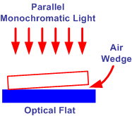
For elliptical flats – the flat is compared against a known good reference flat. This is done by taking a known good optical flat and just simply laying the elliptical flat to be tested on top of it. The air trapped between the two glass surfaces is sufficient to cause a slight angle and generates fringes. With this set-up, the fringes are 1/2λ apart. From the resulting fringes, the quality of the flat can be judged. In the case of a flat we are looking for straight fringes.
An Interferometer has to be more complicated because the reference flat and the piece under test are physically separated.
There are several ways to construct an Interferometer and we have chosen one method to describe in detail. We chose this method primarily because we feel it is more straightforward. Once the principle behind one type of Interferometer is understood, it should be easy to understand the other types.
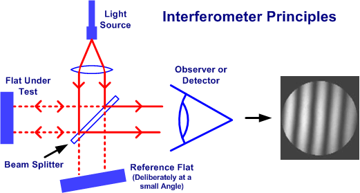
In this method – a point light source is first converted to parallel light using a lens system and fed to a beam splitter. Part of the split beam is reflected off the reference flat and part off the piece under test. The two returning light beams are recombined and fed to the observer or a detector like a CCD Camera.
Usually there is a deliberate small angle on the reference flat to generate fringes. Instead of the “Mk1 eyeball”, the detector in an Interferometer is usually a CCD camera. This takes a picture of the result and feeds the information into a computer. The computer looks at the various blacks, whites and shades of grey in the picture fed from the camera. We understand it tries to locate the centre of the black fringes. It then decides if the fringes are straight lines and each straight line is a constant distance from its neighbours. If it sees deviations from straight lines, or differences in distances between the lines, it works out what the deviations mean in terms of error on the mirror surface.
It is admitted the final results are presented in a far better form than any Double Pass Null Test! – You can have coloured 3D pictograms and tables of figures attractively printed out. This all sounds simple, but there are hidden issues in the system that are virtually never explained.
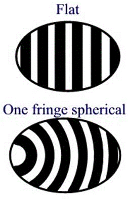
The CCD camera is reporting levels of black, white and shades of grey to the computer. The sample picture above is very typical of such a picture. Although it is a good picture – look closely – Note that it is not even and has differences in the shadings of grey across the lighter areas. This is not too bad if the fringes are straight and towards the centre of the picture. The computer must estimate where the centre of the fringes are and if the fringes are straight and well away from an edge the computer processing may deal with the shadings fairly well. However – we suggest the technique has problems at the edge of the mirror. Here it may have only part of a black fringe with no “white” area outside it to use as a reference when fixing the fringe centre. It cannot be as accurate in these areas.
If it makes an error in estimating where the centre of the fringe is, then the results will suggest the mirror has errors at these points around the edge. To give evenly lit pictures the Interferometer must have a light source and collimation system that gives a very even brightness across the full field of view of the beam splitter. In practice the single lens system shown in the diagram above would certainly not be sufficient. It is not often considered that the CCD camera used as the detector must have a very equal response from all its pixels. Problems with uneven lighting or pixel areas in the detector with different responses have the potential to affect the results. Even if the lighting and CCD camera are perfect, it is possible that air movement at the time the test picture is taken may affect the results. This could in theory be countered by taking a number of pictures and comparing them to see if air movement was an issue. However our opinion is that it is not as good as the human eye and brain used in the Double Pass Null test, which views the results over a few seconds and discards air movement.
Spherical & Parabolic Shapes
The description above is of a flat surface, there are additional complications to test a spherical or parabolic surface. The usual technique is to convert the flat collimated light beam from the beam splitter to a spherical Wavefront with an additional lens. To give the greatest accuracy, the lens must have a F/ ratio slightly faster than the mirror under test. A very accurate lens is needed to convert the collimated light beam to a spherical Wavefront within say an accuracy of least 1/20λ and the reference flat within the Interferometer needs to be better than that accuracy.ù
Then assuming that a double pass system is being used, the optical system is as below.
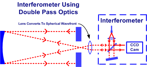
There are now three elements instead of one that need to be extremely accurately made. There may also be problems aligning the optics. Counting the Interferometer optics as one unit, there are four sets of optics to line up and space correctly.
It is necessary to:-
- Line up Interferometer, Parabolic Mirror & Lens accurately on the same axis
- Check Parabolic Mirror, Optical Flat and Lens are each set at 90 Degrees to the axis
- Check distance between Mirror and Lens exactly correct
You need to be extremely accurate with these settings because you are looking for errors less than 1/10λ. If any of these settings are wrong the Interferometer will give an incorrect result. Anything off axis will suggest Astigmatism in the mirror. Anything not at 90 degrees will suggest Coma.
Examples of how small an error in positioning an optical element and the error it causes are given later.
There are controls on the Interferometer that use internal software to attempt to correct for set-up errors. There are options to remove “Coma”, “Astigmatism” & “Piston” errors due to set-up. However, we suggest that there are too many variables in the equations for it to completely null the image. So while these controls can take some of the set-up error out, what is left is reported as errors on the mirror’s surface under test. If you want an accuracy better than 1/10λ, these errors are often significant.
We are not aware of an easy method to “set-up” the full Interferometer system. One method we know of starts by examining the output to minimise “S” shaped fringes. Seeing “S” bends in the fringes suggests coma in the system due to one or more of the optical components not being at 90 degrees to the axis. The tester adjusts settings to minimise the “S” before continuing the testing. If you can see “S” bends in the Interferometer report, its extremely likely it was not set up accurately.
It seems setting-up an interferometer is really trial and error. The various optical parts are shifted around until the errors seem to be at a minimum that gives the straightest fringes. The problem in doing this is that the error on the mirror is extremely small to start with. It can easily be covered up by the set-up errors. Those errors may interact with each other and the real error to produce a false minimum, which the tester cannot detect.
Setting up an Interferometer is more difficult compared to a double pass Null test. We are not saying it can’t be done, but it is highly skilled and, if it is not done properly, the results from the Interferometer will suggest the Mirror is a lot worse than it really is.
Oldham Optical has attempted at various times to talk with some of the interferometer testers. We have found it extremely difficult to get meaningfull information on either the optical arrangements, the method of setting up the test, or how the interferometer software attempts to eliminate set-up errors. I am afraid our experience has been that the testers are unwilling or unable to answer detailed questions.
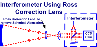
A parabolic mirror can be tested at the centre of curvature instead of at the focal point, but in doing so the accuracy drops by at least half. The large optical flat is not required, but if nothing else was done to the optical arrangement, there would be a large amount of spherical aberration.
To counter this, an extra lens known as a “Ross Correction Lens” can be inserted into the system to correct for Spherical aberration.
This means there is yet another very accurate optical part needed and that also needs centring and lining up accurately with the other optics. But this is a common method used by interferometer testers to avoid the expense of an optical flat.
It is possible to simulate the set-up of the various optical elements and then move one of them to see the error it introduces. Using the ray tracing programme Zemax, we have set up an example of a parabolic mirror with a Ross lens being tested at the centre of curvature.
Continue