If you are constructing a Cassegrain telescope, you will have to collimate it in the final stages of construction. This means setting the two mirrors in line exactly on the axis of the focuser and at 90 degrees to it. Even if you buy a ready made telescope rather than constructing it yourself, you can expect to have to collimate it when you receive it.
You may also have to re-check your Cassegrain at intervals, especially after a large one has been moved. The first part of this page explains the adjustments you must build in to the telescope during construction so you can eventually collimate it properly.
Critical Dimensions
Or conversely, when ordering optics for an existing telescope, you must specify the critical dimensions to the optics manufacturer for him to build to.
The two critical values are the separation distance between the mirrors and the vertex back focal length.
Oldham Optical measures the values from the mirror surfaces as in the diagram. Most other suppliers probably measure from these surfaces as well, – but no harm is done by confirming where the measurements are taken from.
If you stray far from the dimensions specified, it is still possible to focus the system and get good images from a star on axis, but you will lose some of the performance off-axis. In particular, Ritchey Chretien coma free optics are designed for a fixed separation between the primary and secondary mirrors to operate properly.
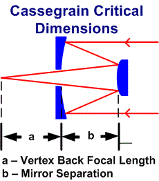
If your telescope focuses by altering the separation between the two mirrors, then a few mm either side of the optimum value wont make any difference in practice. However, if planning to use something with a wide field (like a 35mm camera, or bigger), then design the focuser and camera fittings to keep close to the correct dimensions when using the camera. This may mean some compromise for direct viewing with eyepieces, but these involve narrower fields, so should not be a problem.
The telescope when assembled may enclose both the primary and also the secondary mirrors, so if practical try and sort out during the construction of the telescope a method of measuring the two dimensions easily.
Perhaps a hole might be provided through the mirror cell close to the focuser allowing the distance from the back of the telescope tube to the back of the primary mirror to be measured. The hole can be blanked off afterwards with a screw.
Perhaps the position of the secondary mirror could also be measured to some reference point on the outer telescope tube?
Primary Mirror Lateral Adjustments
Its not that common, but is covered here in case. It is possible to provide the primary mirror with proper lateral adjustments for “Up and Down” and “Side to side”.
These can be used to set the primary mirror on axis with the focuser. If the mirror is hung from a strap, then varying the length of the strap provides a simple “Up and Down” adjustment. Don’t worry if your telescope does not incorporate this feature, but if it has full or partial adjustment, be prepared to take advantage of it later. It will be used to centre the hole in the primary mirror over the focuser.
Primary Mirror Tilt Adjustments
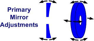
What the primary mirror must always have is a means of tilting the mirror to set it to exactly 90 degrees to the axis.
Similar arrangements to a Newtonian are often used.
There are plenty of photographs and designs available of mirror cells for Newtonians, but they usually boil down to some form of three point suspension.
Usually each of the three legs has an adjustment. Varying the lengths of each leg allows the tilt of the mirror to be adjusted so as to set the mirror to exactly 90 degrees to the axis of the telescope.
The ability to tilt the mirror is needed in both X & Y directions, as the diagram adjacent done separately in 2D and 3D tries to show.
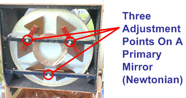
An example of how to do it is in the next photograph. The picture is of a big Newtonian, but the principle applies to a Cassegrain Primary mirror as well. The three points supporting the mirror can be seen.
Each has an adjustment by screwing or unscrewing the appropriate nuts which enable the mirror to be tilted as required so as to set it at exactly 90 degrees to the axis of the telescope system.
These adjustments are used to minimise coma in the final part of collimation.
Secondary Mirror Lateral Adjustments
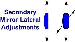
All large Cassegrain telescopes should have a means of adjusting the secondary mirror physically “Up and Down” and “Side to Side” to set it exactly on the telescope axis. Small telescopes may just rely on the basic mechanical engineering to set the mirror on axis.
This is often (but not always), done with an adjustment on the spider that holds the mirror. This adjustment will be eventually used to centre the mirror on the axis of the telescope.
There are no apologies for using a Newtonian as an example. It’s exactly the same principle for a Cassegrain and good pictures of one of David Lukehurst’s big Dobsonians are readily to hand.

Secondary Mirror Tilt Adjustments
If your telescope mirrors are figured for any Cassegrain that does not use a spherical secondary mirror, then you must have adjustments to adjust the tilt of the secondary mirror. This is also very useful but not quite as essential for a Dall Kirkham. A smaller scale arrangement to that used on the primary mirror may be used.
Although its not fashionable at the moment, – the best way to hold a Cassegrain secondary mirror is to manufacture it with a central hole. The mirror then fits over a post attached to the spider. The centre of the mirror is never used optically so there is no loss of light and there is no cell needed to hold the mirror which would otherwise increase the obstruction ratio of the telescope. If you are thinking about building a big Cassegrain, – then talk to us about holding the secondary.

Tools For Collimating The Telescope
You now have a telescope constructed with all the adjustments. the mirrors have been put in place and it is ready for collimation. You have simple tools such as the right spanners, screwdrivers etc at hand to operate your adjustments.
There is one special tool you will need to make to assist in collimation. This is a pinhole. The focuser of the telescope must be fitted with a disc with a small pinhole in it of say 2mm diameter. The pinhole must be dead centre on the axis of the telescope.
The disc and pinhole must have arrangements to fit it to the focuser so that the pinhole is on the axis of the telescope. Where the focuser will take 1¼” eyepieces, or a reducer can be fitted to take such eyepieces, a standard plastic 35mm film canister can be converted to be a pinhole.
A 35mm canister happens to be a snug fit in the focuser. Cut off the bottom of the canister with a hacksaw and drill a 2mm hole dead centre in the lid. The device is now ready for action.
35mm Canisters are getting rare now digital cameras are taking over, but take a trip to any high street photographic developer such as Boots, and ask nicely at the counter and we would be surprised if you can’t get a hand-full for free.

There is a slightly more sophisticated version that makes collimating a Cassegrain slightly easier.
The picture adjacent is one of the more “sophisticated” type. This one is based on a 35mm film canister for the outer tube and the inner tube used to be the core of a sellotape roll.
It’s not designed to be telescopic! The translucent section allows light to penetrate the tube making it easier to adjust the tilt of the secondary mirror. The same thing could be achieved by cutting the 35mm film canister in half and sellotapeing the two halves back together, but with a gap between them.
Note you may have a very expensive telescope, but the point being made is that it does not need expensive equipment to collimate it. This class of device is good enough for the very best – and so suggest it’s probably good enough for you.
If you have a large focuser without a reducer, then you must make or engineer your own device before you can go any further.

Initial Set Up
The main part of the setting up procedure should be done inside a house or garage in good daylight. The telescope should not be set up looking out of a window or at any other bright light source as you will be looking through the tube from the area around the focal point using the pinhole.
You do not want to risk damaging the retina of your eye from inadvertently looking at bright lights!
Start by going through and loosening any lock nuts on the various adjustments.
Check the critical dimensions (again). These are the Vertex Back Focal Length & separation of the mirrors.
Check by simple measurements or a visual check that the hole in the primary mirror is central about the focuser bore. If there is any lateral adjustment on the primary mirror, use it to centralise the mirror on the focuser.
Check by eye and perhaps simple measurements from any fixed points on the OTA tube structure that both mirrors are set as close to 90 degrees to the axis as possible. This does not need to be exactly correct at this stage as it will be checked later.
If your telescope has lateral adjustments for the primary mirror, then adjust them by eye so that the hole in the primary mirror is centred over the focuser.
Fit the pinhole to the focuser and put your eye close to it. Rack the focuser in and out until you obtain a view through it as in the diagram opposite.
In the diagram the black area represents the inside of the focuser tube. The outer blue area represents the back of the primary mirror. The inner blue disc is the secondary mirror viewed through the hole in the primary.
Once you can see the hole in the primary mirror and the secondary mirror clearly, rack the focuser in and out so the hole in the primary appears only slightly bigger than the secondary mirror.
You are now ready to adjust the secondary onto the same axis as the focuser and the primary mirrorA warning first! All this can be easily done with the OTA lying on its side with the optical axis horizontal. Don’t perhaps be tempted to angle the tube upwards to get at the secondary mirror adjustments more easily. If you drop a spanner when the secondary is above the primary, it is likely to smash the primary mirror! So keep the tube flat such that if you do drop a tool, its not going to fall on anything expensive. Think through what you are going to do first.
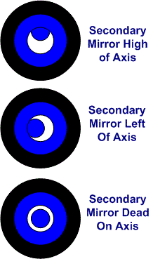
You have to centre the secondary mirror in the hole in the primary as you see it through the pinhole. This is done by adjusting the secondary mirror lateral adjustments described earlier. It should be a fairly straightforward task to centre the secondary mirror in the view.
If your telescope has no lateral adjustments on the secondary, but has them on the primary, use these to line up the axis instead.
When you have finished, the focuser, the primary mirror and the secondary mirror are all set on the same axis.
Adjusting The Tilt On The Secondary Mirror
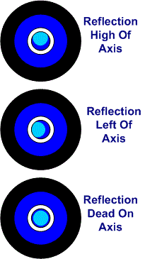
Look through the pinhole again and concentrate on the view of the secondary mirror. On the face of the secondary you will be able to see the reflection of the focuser entrance. If you have the more sophisticated pinhole that allows light in as a circular ring, then you will see a bright ring around the central axis, otherwise you will just see the black hole of the focuser.
Alternately, you should also be able to see the reflection of the primary mirror on the face of the secondary. This can be used instead.
Adjust the three Secondary mirror tilt adjustments as necessary to centre the reflection of the focuser and/or the primary mirror, on the centre of the secondary mirror. The diagram adjacent assumes you are looking for the reflection of the primary mirror, which is shown here as light blue.
The process of adjustment is fairly easy, but the first time you do it you will have to experiment to find out which leg moves the reflection the way you want it to go. Once you have seen how the reflection moves, you will quickly zero in on the adjustments that move the reflection on to the axis.
If you need a bit more help in starting:- first note the direction that the reflection is most off axis and choose the leg that is pointed nearest to that direction.
There are three legs spaced at 120 degrees, but since they can move either forwards or backwards each also covers the direction 180 degrees out of correspondence. So choose the leg that is either pointed nearest to the reflection or at 180 degrees from it.
When you have adjusted the first leg to a minimum, the reflection will almost certainly still be off centre, but it should be exactly lined up with one of the remaining two legs. Adjust that leg to centre the reflection dead on axis.
Do not adjust the remaining third leg. If after moving the second leg you cannot completely centre the reflection, return to the first leg you moved and adjust that. Repeat moving the two in turn until you are happy you have the reflection centred.
Some of you may be surprised that using the view of the reflection is sensitive enough to set the secondary mirror tilt accurately – Most of the coma will come from an inaccurately set primary mirror and that is adjusted later.
Check Critical Dimensions Again!
Once you are happy the reflection is correctly centred, get out the tape measure again and measure the critical dimensions:
Separation distance between the mirrors and the vertex back focal length.The act of tilting the secondary mirror could have altered these dimensions slightly. If necessary, compensate by moving all three adjustments on the secondary mirror by exactly the same distance in the opposite direction. This will shift the secondary mirror axially to get the mirror separation right without affecting the tilt.
Tighten up any lock nuts.
You have now nominally finished the in-door set-up but it would be sensible to go back and run through the same procedure at least once to check everything is still OK. The next job is the star-test.
Adjusting the Tilt Of The Primary Mirror
This job is done while viewing the stars. You will be working outside at night and it’s going to be dark!
Take this section very steady and do one thing at a time.
Have a routine for putting down any tools in one place so you can find them again.
Think through all the motions and movements first.
If necessary, practice the actions in daylight first.
First, loosen any lock nuts on the primary mirror adjustments.
Set the telescope up with a high power eyepiece and focus it on a star in the centre of the field of view.
There are plenty to choose from!
Rack the focus backwards and forwards through the position of best focus and you should be able to see a disk and ring structure on either side of focus.
This is comprised of the Airy Disc and diffraction effects from the central obstruction of the Cassegrain. Study the ring system either side of focus.
If the primary mirror is tilted correctly, there will be no coma in the system and the ring and disk system will be concentric either side of focus.
If the primary is not set correctly, there will be coma in the system which will show up as the disk and ring structure not being concentric. It will be offset in one direction on one side of focus and shifted 180 degrees on the opposite side of focus.

The disc and ring structure will probably not be exactly as depicted. What you see will be dependant on the telescope itself, diameter, focal ratio, obstruction ratio, eyepiece etc. The central disc may appear larger or just be a central dot. There may be more rings visible than shown. What you are looking for is any basic disc/central dot and ring structure that you can see is concentric either side of focus.
If you can’t initially see a ring structure, try reverting to a wide angle eyepiece and look for uneven brightness in the disk either side of focus.
Coma will be removed by adjusting the tilt of the primary mirror. Note the axis of the coma. In the diagram above it is running top left to bottom right. Choose the leg of the Primary that is closest to the 60 degree sector of the axis of the coma. Adjust it one way to see if it improves it. If it makes it worse, move it back the other way and adjust it backwards and forwards as necessary to reduce the coma to a minimum.
When you do reach a minimum position from adjusting one leg, – the axis of the remaining coma should be lined up exactly with one of the two other legs. Adjust this one to remove the remaining coma.
If adjusting the second leg does not completely remove the coma, return to the first leg and re-adjust that nearer to a minimum. Repeat with the first and second leg as necessary to completely remove the coma. Do not adjust the third leg.
Tighten any lock nuts when you have finished and check for coma again.
Once you have removed the coma, the primary mirror will be accurately set at 90 degrees to the axis. So take the opportunity to do a bit of observing – Have a coffee or perhaps something that comes in a glass and is a bit stronger! There is still a job to do in the morning, but that can wait.

The Morning After?
It doesn’t really have to be the next morning afterwards of course, but it is a job for the house or garage in good daylight. Do yet another check of the critical dimensions: Separation distance between the mirrors and the vertex back focal length.
The act of tilting the primary mirror could have altered these dimensions slightly.
If necessary, compensate by moving ALL three adjustments on the primary mirror by exactly the same distance in the opposite direction. This will shift the primary mirror axially to get the mirror separation right without affecting the tilt.
You will want to check for coma again when you next start observing, but it’s unlikely to need any tweaking and you will be an expert at the adjustments by now.
Perhaps its time for yet another glass of something a bit stronger?