I’ve always been a keen Moon and planets observer, I started in 1980 with a Konus Alcor, a 114 mm Newton and then I replaced it with the glorious refractor Vixen 102M achromatic.
Then years later I bought a 150 mm f 10 oil-spaced apochromatic refractor from Zen, and a truss tube manufactured to specific requirements and then sold possibly because of a disagreement between the customer and the manufacturer who made the tube (the telescope was in Observatory). In fact the tube was really awful, when I first looked at it I nearly died. I remember that the diaphragms were cut with plumber’s tin snips, you can imagine the focuser and all the rest! Anyway, I accepted the offer knowing that I would have had to replace the truss tube but, twenty years later, I am satisfied owner of a fantastic apochromatic which has given me lots of enjoyment.
Living on a plain, far from lakes and mountains, the Seeing conditions are normally good enough for me to observe during most nights of the year and , for this reason, a couple of years ago I bought a 316 mm Dall Kirkham from Romano Zen with f 5 primary mirror and 6 mt focal length.
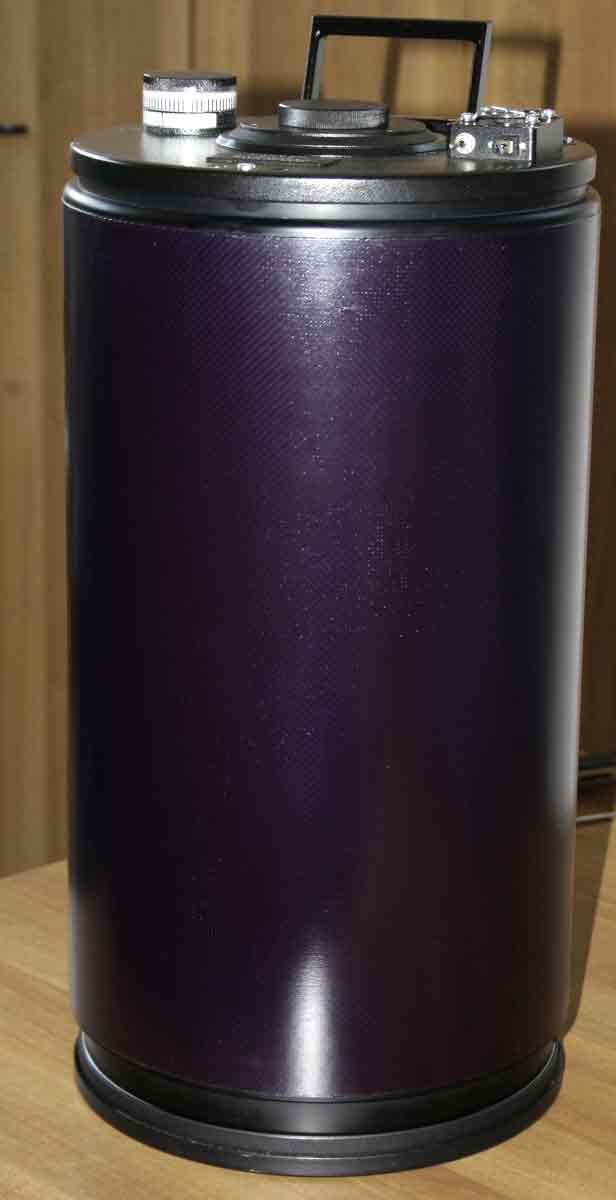
The tube is made of 3 mm thick calandered aluminium, whit 1350 mm length and 350 mm external diameter. Two rings, holding the breech and the secondary support, are positioned inside the tube at its two ends. The breech doesn’t have any cooling fan and there are only 15 mm between the tube and the boundary of the primary mirror.
The instrument was positioned in an outdoor shed however, because of the glass mass which could hardly achieve the thermostation and an inner turbulence, probably due to air columns inside the tube; I could only use it few nights a year.
The images supplied by this instrument are more wavering and less sharp than those of the refractor even during nights with a good Seeing. Although it is true that the bigger the telescope the more sensitive it is to the atmospheric turbulence which removes easily attainable details, the turbulence itself shouldn’t conceal details that even a smaller sized telescope would be able to achieve in similar conditions.
The questions was complicated and I didn’t know what I could do. During a web search I accidentally found the NortheK website, a company producing optics, mechanics and composite materials in the astronomic field, which I’d never heard of before in any of the various forums or astronomic magazines. After reading carefully all the technical topics discussed in their website I realized that I could have possibly found an answer to my problem. So, I called Massimo Boetto, technical advisor of the Maxproject Team, and since then we started a cooperation that became a friendship with both Massimo and his brother Mauro (high precision engineering designer).
They suggested assembling my Dall Kirkham optics with the truss tube UnitorK 35 and replacing the secondary mirror’ support (which was glued to the tube) with the model AxyS A1.
In the meantime, as I had the opportunity to work in an engineering workshop with the help of a turner friend, I decided to replace the cell and the primary baffle. In fact, the baffle was fixed directly onto the breech excluding any possibility of centering the primary mirror which was then blocked in tension whit a ring nut. The focuser, a 400 euro JMI Cryford, was screwed directly onto the breech. Nothing extraordinary but there was a problem: among many advantages it had a weakness typical of most commercial focusers, between the body and the sleeve where the focuser would slide there was a gap, in my case, of nearly 0,5 mm! When the focuser is linked directly onto the breech the body is on an axis but the sleeve, where all the accessories are inserted, is 0,5 mm out of axis.
After making these modifications, the primary’s cell, its baffle and the focuser, have been all positioned inside a precise mechanical system and they can be individually adjusted. In this way, all the mechanical adjustments allow the preservation of the axis, the optical set can be adjusted with small movements of every element, included the focuser which is now connected to the telescope through a tilting flange.
Once the truss has been delivered with AxyS A1 support, I have assembled and adjusted all the mechanical components using a 300 mm centesimal dial gauge, added the optics and collimated the whole system. The instrument has now a total weight of 32 Kg. In assembly I could appreciate the making, the finishing and the material used for “naked” truss structure, a totally open serrurier with aluminium bars (the original project would use carbon fibre bars). The structure is 1335 mm long, 500 mm wide and 18 Kg in weight. Every component of the tube has been made with material fit for the purpose: Halo 25 alloy, stainless steel, and self-lubricant matrix technopolimers. I was pleased to notice that the strong Losmandy type bars (AW 361) ware included in the project (2).
The support for the secondary mirrors AxyS A1 is included in the UnitorK system. This is a very complex mechanical piece featuring a horizontal shifter with 0,02 mm accuracy, a double support made in Halo 25 alloy and a 3 spokes support which gives strength to the system. The optics is positioned onto a barrel featuring a rubber o-ring at the front to hold the system and some felt inside leaving the glass disc free to expand. The centring inside the barrel is done with side adjustments with a thermal expansion control system.
Because of its large focal length, this instrument is ideal for visual observations and big magnification imaging. The 32% obstruction is quite a high ratio but we shoudn’t forget that the diameter and the baffle length of the two mirrors have been designed to remove the side light which could get through the eyepiece field and therefore degrading the instrument performance (certainly more than what a lower ratio obstruction would have done).
In order to remove the reflection which generates diffuse light, the primary’s baffle has been made with seven especially designed cone light diaphragms, while secondary’s baffle has been made with a diaphragm that takes the light cone to 79 mm. In order to remove any faults on the primary’s raised edge; a turned aluminium ring has been positioned on it reducing the aperture to 310 mm.
One of the picture published below shows an unusual link between the focuser and the binocular turret: it is a highly precise mechanical piece specifically designed to keep any accessory on axis and, inside it, there is a light cone diaphragm. This is an alternative proposal to the traditional 50.8 mm link systems which, more often than not, are made with excessive tolerances leaving accessories and eyepieces regularly out of axis.
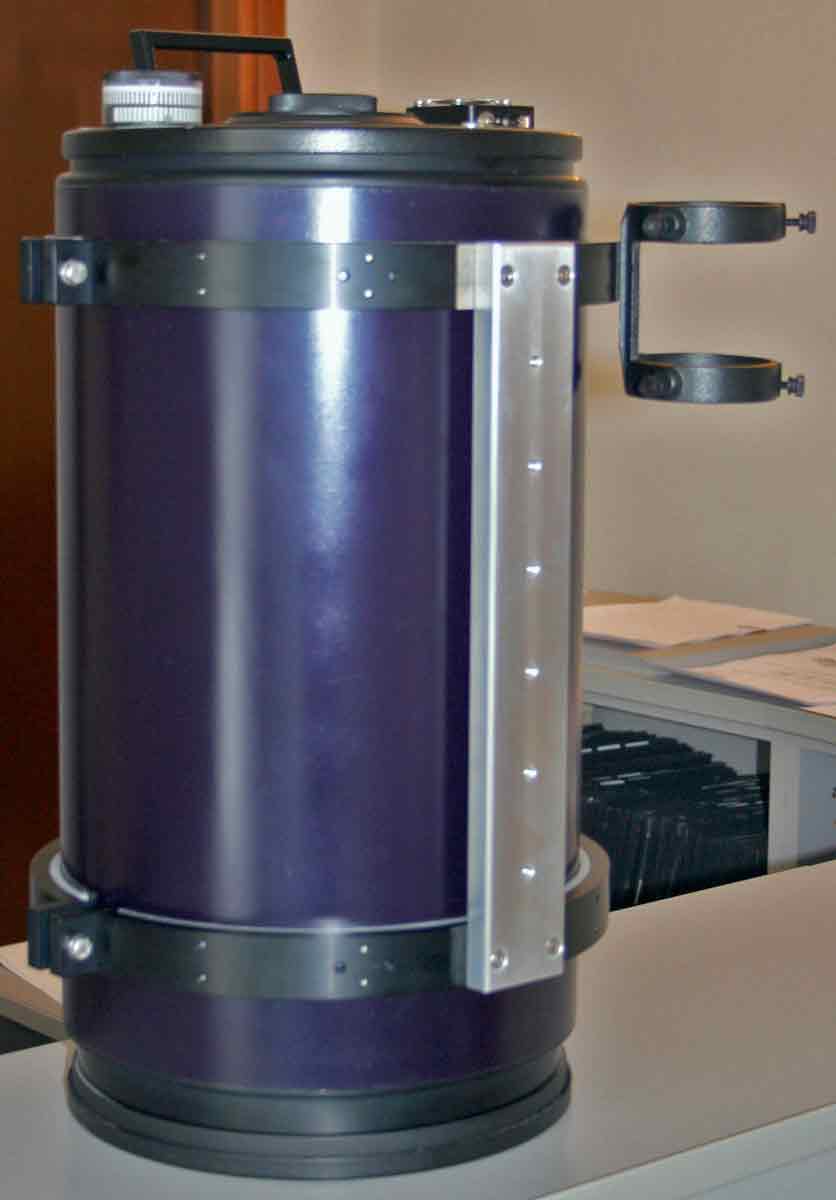
Another very useful mechanical piece is the micrometric system positioned between the clamp and the Losmandy slide (AW 361). This piece helps the balance of the telescope in declination (as this system has only recently being designed it still needs some aesthetic improvements). How many of you would be able to balance the axes in declination on a German equatorial mount holding a 32 Kg telescope? Believe me, this accessory allows one person only to do the job easily and safety!
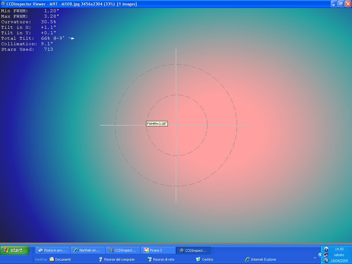
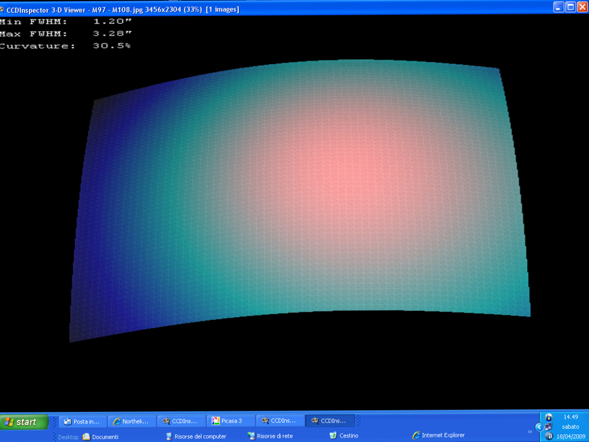
Star test.
The star test has been carried out observing a star high in the sky at 1150X during a good Seeing night, using a mirror diagonal with a Pentax XL 5.2 mm eyepiece. The mechanics allow me to collimate the optical train in a simple and precise way even with unbelievable magnification! The intra and extra-focal diffraction images are almost perfectly identical; no zonal error or residual spherical aberration were detected. Incredibly the atmospheric turbulence has disappeared and the star images are in focus and quite sharp so the aim has been achieved brilliantly, not only, during my observation night I never noticed the warm air column and heat wave distortion effects that I was sadly used to.

Although the conic primary mirror doesn’t normally have an even differential of thermal stabilization because of its thick centre and thin edges, the solution suggest by the NortheK technicians to leave the optics exposed to the air has been proved right.
In order to be able to use the Mark 5 binocular, I adjusted the back focus by simply turning the knob of the AxyS A1 horizontal shifter with 0,02 mm accuracy and I could observe Saturn with a couple of 18 mm Ortho Genuine eyepieces at 340 X.
To make sure that the mechanics could keep the axes in parallel and therefore preserve the collimation, I focused on the planet perfectly on the meridian side and I tried to overturn the telescope on the other side: incredibly Saturn was still perfectly in focus! The generous diameter of this instrument made it particularly good for moon observations. I used the Mark 5, which I can’t do without for my visual observations anymore, with 12.5 and 7 mm eyepieces Ortho Genuine (480X – 670X – 860X) and I could experience the tridimentional sensation that this accessory offers but, most of all, I noticed the total absence of diffused light. The instrument can now offer very detailed and contrasted images showing fine details such as Rilles, mountains, ridges and lots of small craters “invisible” before have now become visible….this time the challenge between the apochromatic and the reflector, unsurprisingly, has been won by the reflector!
See you soon!
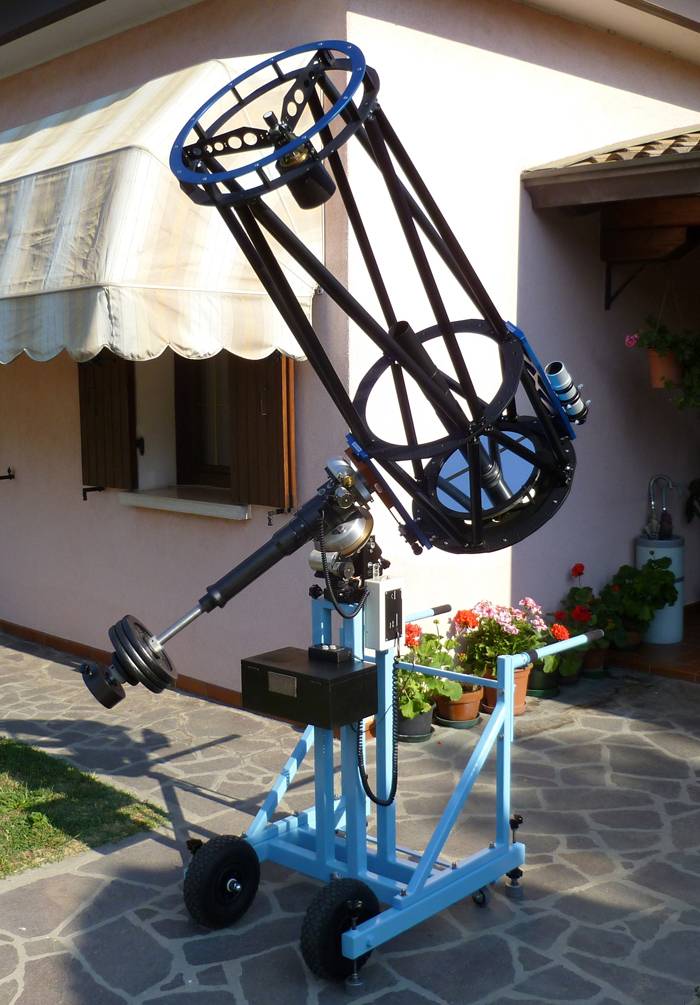
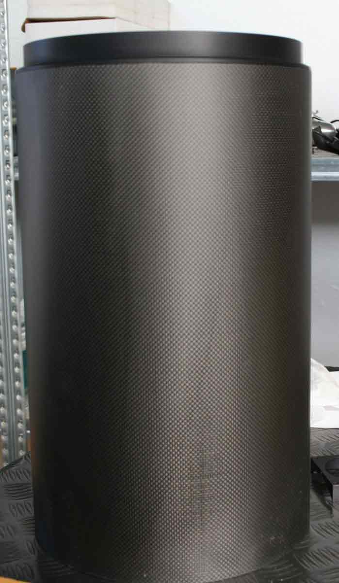
The telescope on the top of the self-made German equatorial mount.
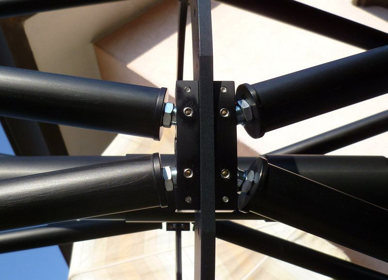
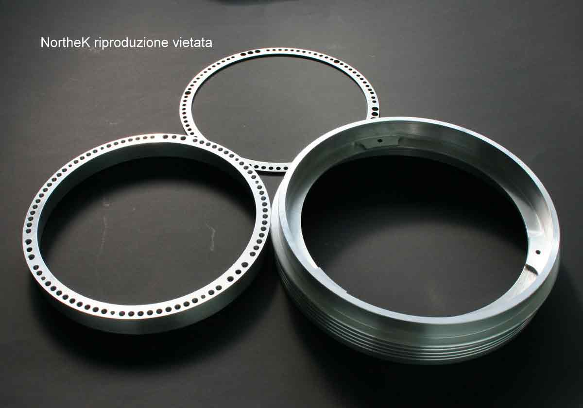
Link on the UnitorK 35 system. Please note the precision and the accuracy of the construction.
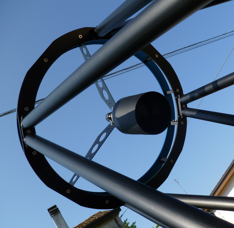
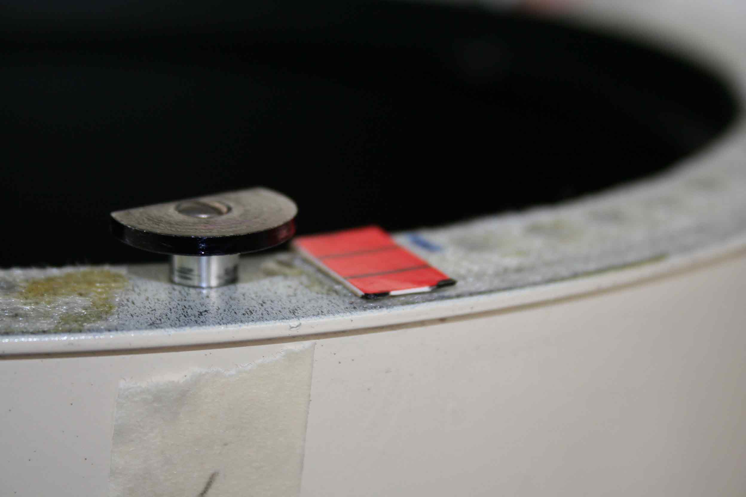
The AxyS A1 support seen from the secondary mirror, please note the absence of any reflection inside the baffle.
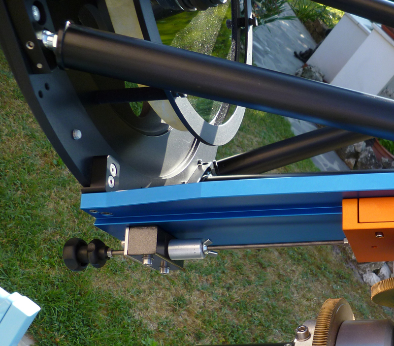
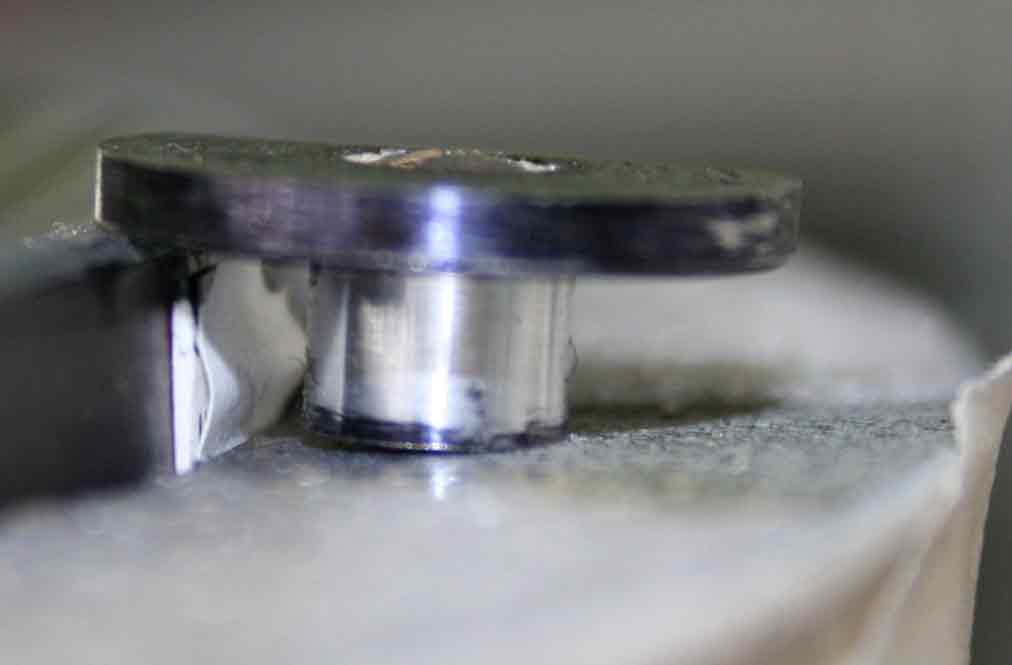
The micrometric system positioned between the clamps and the slide AW 361. Very useful to balance the axes in declination.
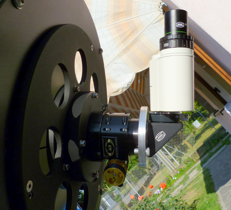
Unusual link between the focuser and the prismatic diagonal Zeiss.

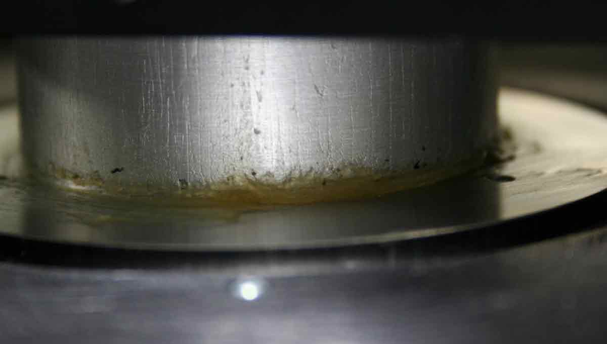
The new baffle: please note the 8 mm diameter rubber o-ring holding the primary mirror.
| Optical characteristics | Technical Specifications |
| Optical scheme | Dall Kirkham |
| Nominal optical opening | 310 mm |
| Thickness of primary mirror glass | 51 mm |
| Secondary mirror diameter | 85 mm |
| Thickness of secondary mirror glass | 15 mm |
| Glass of primary and secondary mirror | Pyrex |
| Primary mirror focal lenght | 1500 mm |
| Focal ratio | f 5 |
| Secondary mirror magnification factor | 4x |
| Equivalent focal lenght | 6000 mm |
| Diameter of the 100% illuminated field | 79 mm |
| Fully illuminated field | 18 mm |
| Back focus | 320 mm |
| Actual obstruction including the mechanic | 32% |
| Primary’s baffle diaphragms | 7+1 |
| Secondary mirror holden | NortheK AxyS A1 |
| Truss tube | NortheK UnitorK 35 (alloy version) |
| Maximum diameter of the structure | 500 mm |
| Maximum lenght of the structure, without accessories | 1335 mm |
| Swallow-tailed/plate connection | NortheK AW 361 |
| Standard searcher | 8×50 |
| Focuser | Crayford JMI EV1c |
| Focuser support | Axial adjustable and tilting |
| Cell | Axes and tilting adjustments |
| Primary mirror baffle | Axes and tilting adjustments |
| Primary mirror weight | 5 kg |
| Primary mirror cell weight including baffle | 5,5 kg |
| Unitork 35 weight including + 2 plates AW 361 | 18 kg |
| AxyS A1 weight including secondary mirror | 1.9 kg |
| Focuser EW1 weight including flanged link | 0.9 kg |
| Optical tube weight without accessories | 32 kg |
Roberto Milan ®


.jpg)


.jpg)
.jpg)
.jpg)
.jpg)
.jpg)