Our customer Daniele Cipollina, who is a very experienced amateur astronomer, contacted us regarding some issues with his photographic instrument which never performed. After several unsuccessful attempts to resolve the problem, and considering the cost of the optical tube, our customer has decided to submit the matter to us.

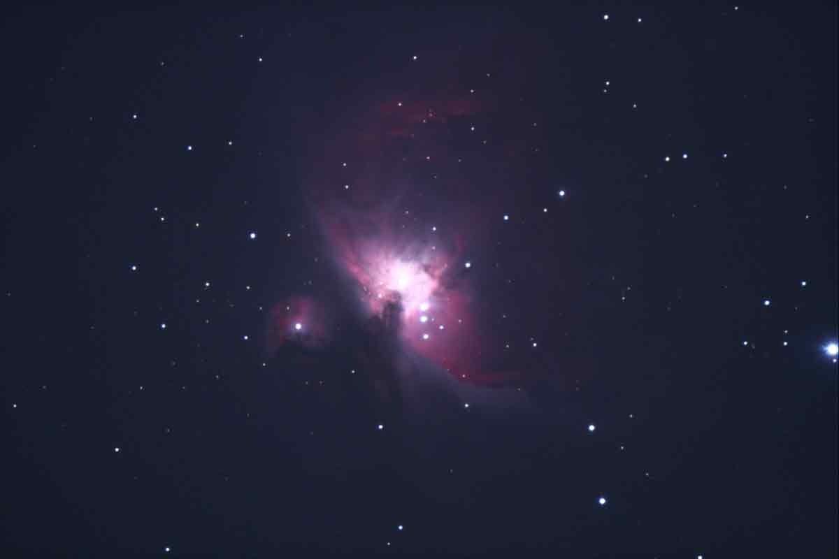
In the trial image above (please disregard the light haloes which are not significant because it is a trial image), a consistent blur is noticeable on the lower right hand side. Moreover, although our espert customer has performed a RIGOROUS focusing with the Bathinov mask, the star puntiformity still remains inadequate for this class of telescope.
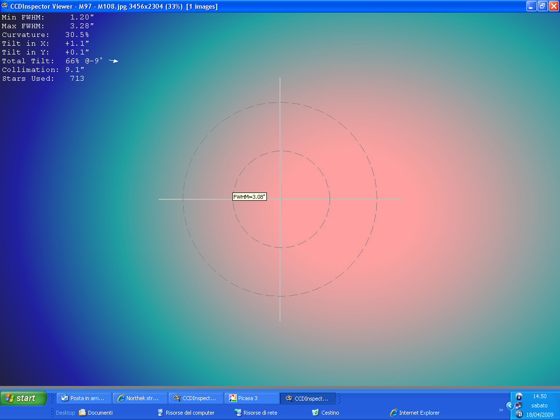
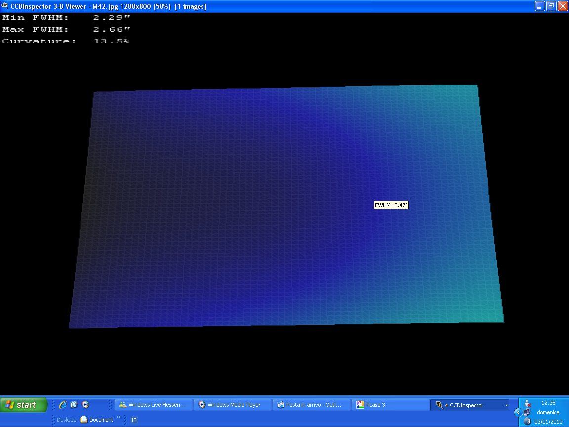
Despite the accurate collimation, the CCD Inspector picture immediately shows a serious distortion. with this condition it is practically impossible to get punctiform images: According to the supplier the cause of the problem is the seeing (!).

The image magnification shows a noticeable distortion on the right hand side of the field edge which results in a poor star punctiformity; this is particularly bad when compared to the telescope price.
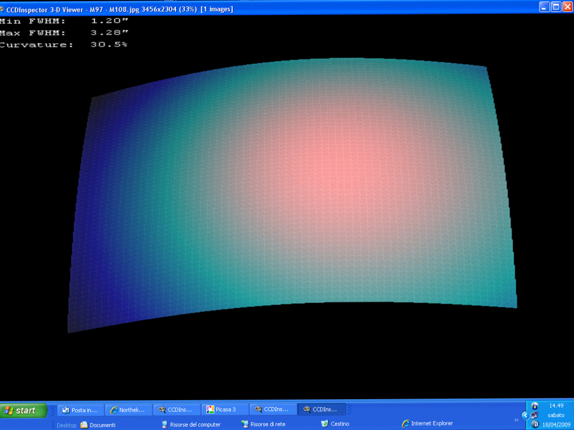
The chromatic dominance is due to the meniscus (and to the turbolence) which was found significantly out of axis from its correct geometrical position.
Although less deformed, the quality at the center of the field is still poor as it is on the left hand side edge where an even worse chromatic dominance is noticeable.
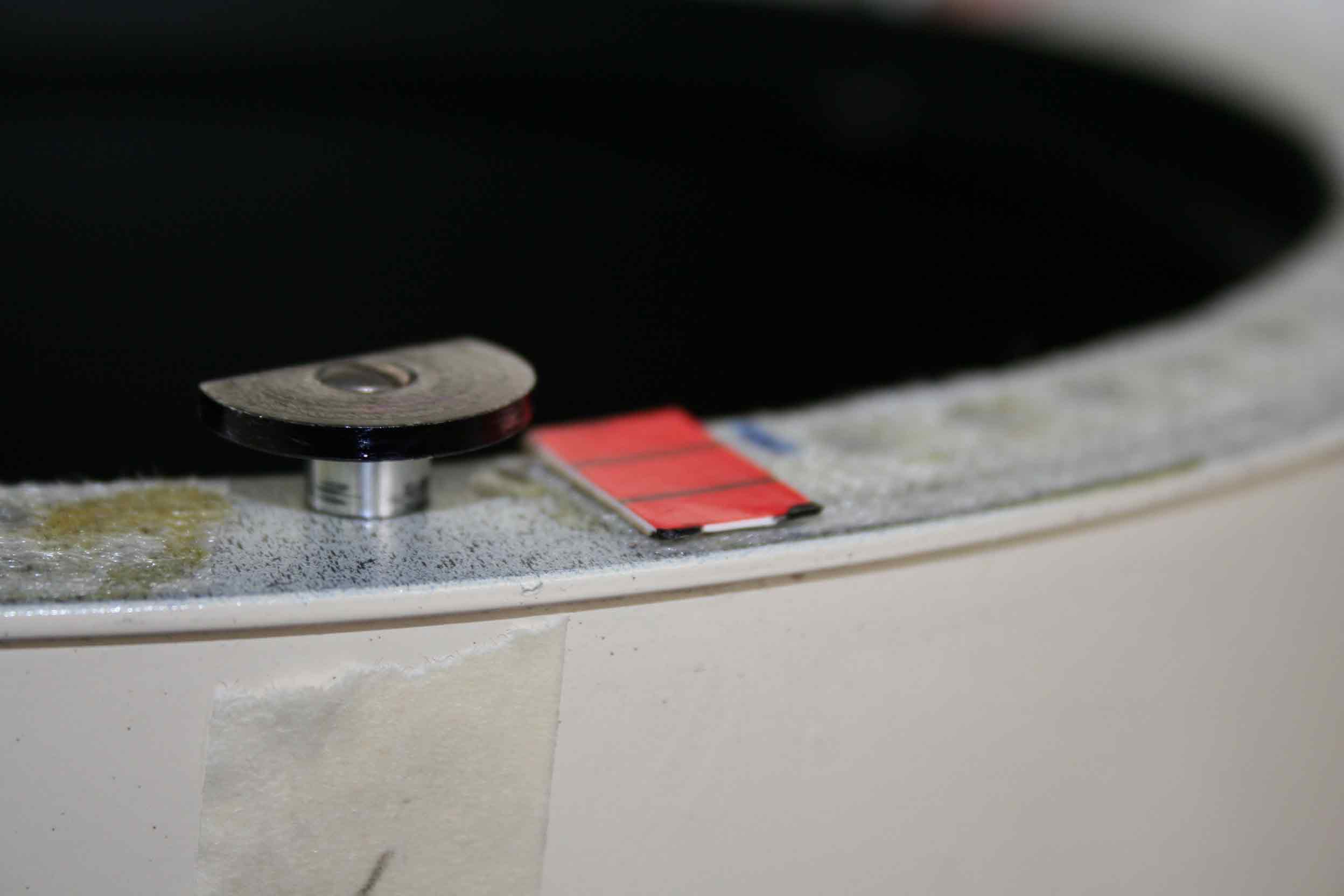
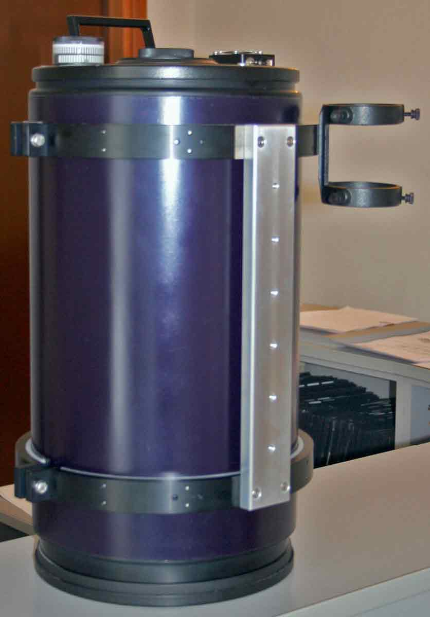
Having dismantled the telescope we could report to the customer the instrument’s conditions as shown below:

Please observe carefully the clamp holding the meniscus. The one marked with the number 1 is fixed and cannot be moved but the other two (positioned 120°) are free to move when they are touched and can be unscrewed. Here is the first clue: the tube edge is not orthogonal.
The meniscus is kept in position by a simple scissor cut cardboard.
Althoug the aluminium tube looks solid from the outside, from the inside it is a simple calandered metal sheet that has been and riveted toghether and the rivets on the outer surface have been ground down and covered with enamel. Two rings positioned at the tube’s ends hold the meniscus and the breech. Obviously the tube is not orthogonal and nor are the rings.
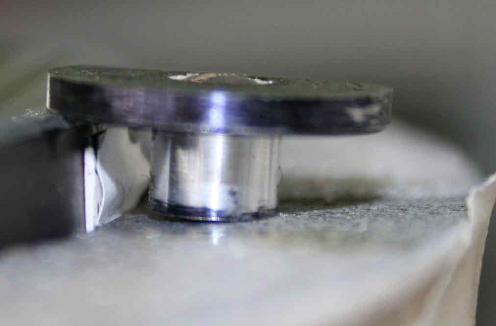
Here you can appreciate the overhelming mechanical approximation. The optical axes are endemically warped.
We judged that the main problem was caused by the axis not being orthogonal. We suggested to the customer to start with a retrofit to achieve effective results avoiding too higher costs. For this reason the breech, the focuser and the corrector have not been changed but the Maxproject Team designed some modifications to be implemented. In this way the cost – still important – was kept under control using effective but not too sophisticated solutions.
The first step has been to replace the calendered aluminium tube with a carbon tube. The reasons for doing this have been the following:
a) The customer wanted to keep the weight under 9 kg (final result 9,7 kg);
b) The use of carbon fiber avoids any thermal expansion of the tube and this is quite important for a photographic telescope;
c) It is possible to fix the setting of the rear cells and to use Epox adesive with 4 hours solidification time directly on the bench;
d) The use of carbon fiber avoids any axial and radial deformation which otherwise will be very difficult to eliminate in such a large tube obtained from a thick extruded metal.
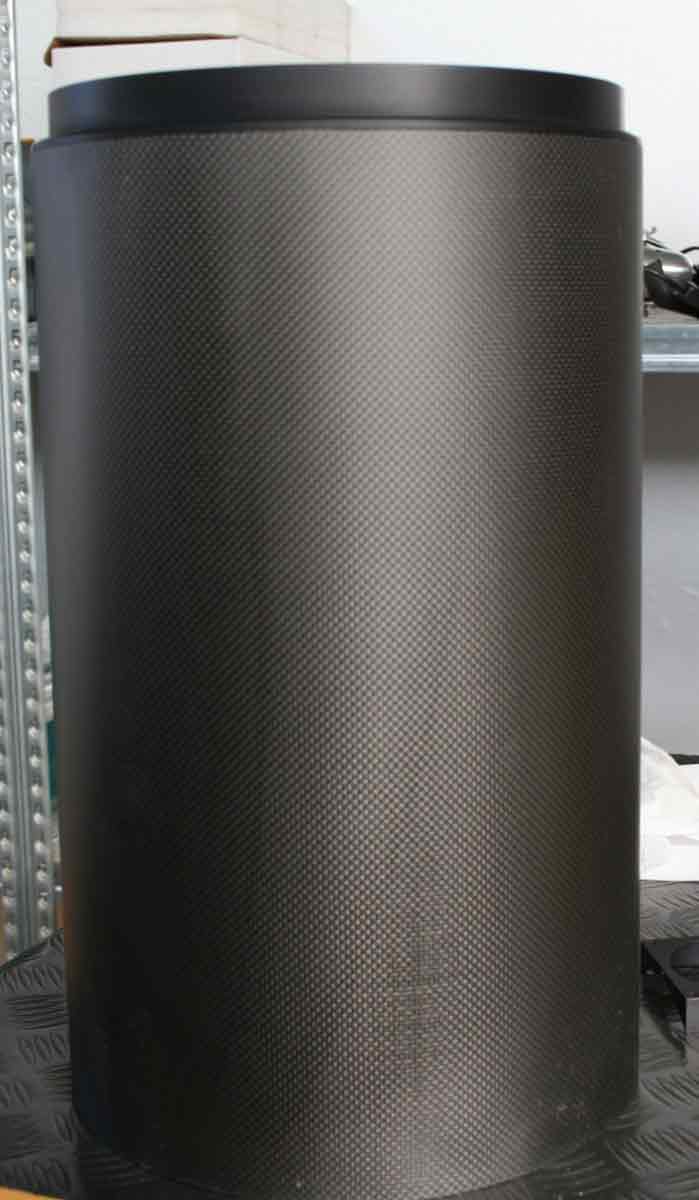
To further avoid any deflexion problem, the carbon tube has been over-dimensioned with a 265 mm internal diameter and 269 mm external diameter, more or less the same as the 10 mm thick aluminium solid tube. The outer surface has then been painted to give it an even more pleasant look. A 0,5 mm tolerance has been used to cut the tube but it is brought back to size when the cells and counter-cells have been fixed to it with epoxy resin/metal.
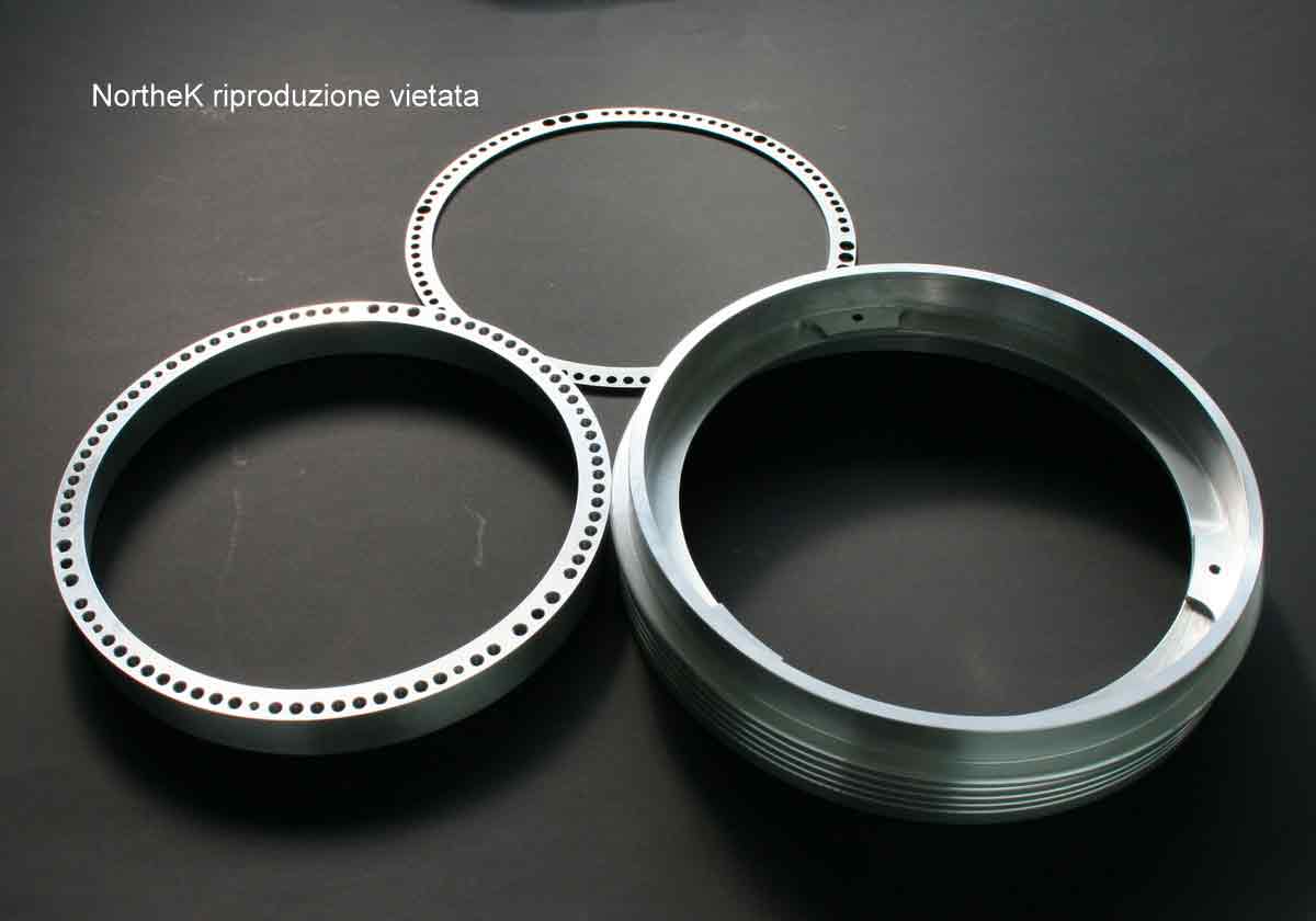
The picture above shows the fixed counter-cell on the right and side. This one is attached to the carbon tube with epoxy resin adhesive (you can see the holes that are use for bonding; other confidential details have been omitted): At the top of the ring it is possible to see the three supports for the meniscus and also the holes where the refrigerating air (then filtered) passes through (again, some details have been omitted). On the left and side there is the meniscus cell – with some omitted details – with aereation holes alla precision engineered to hold the meniscus accurately. At the top the picture there is a simple 2 mm thick pierced stainless steel cover also used to keep the meniscus in position.
.jpg)
This is a cell put in place before being anodized. During the assembly all the tolerances have been checked considering the anodization process. All the components have been produced using numerically controlled machinery with exclusion of the cover which – for cost and actual effectiveness – has been laser cut. A collimation system is also implemented but the pictures are omitted.

Above is the plan view of the rear cell. It has been machined from a solid 60 mm thick piece of Anticorodal. The holes are for the positioning of the diaphragms structure which had to be made for the purpose as the existing one was attached to the original aluminium tube and also over-size.
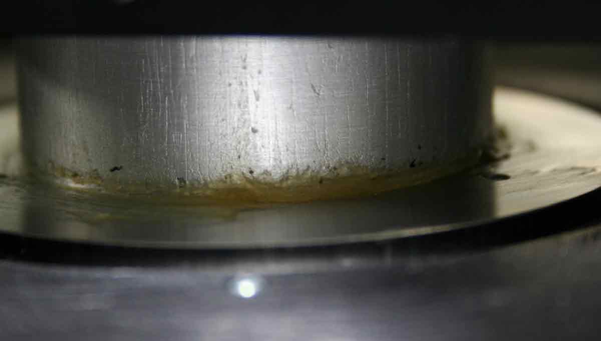
Another problem, pretty common in this kind of commercial telescope, is the use of slightly thermally unstable grease which should ease the slide of the primary mirror inside its sleeve as well as acting as a baffle. Unfortunately, with use, the grease tends to accumulate at the bottom of the sleeve consequently the focusing movement can jerk and, being no longer smooth, it doesn’t help with the search of the best punctiformity. Unless external focusers are used, this grease should be replace periodically after cleaning.

The anti-reflex diaphragms structure is applied to the rear (please note the thickness) and kept separate from all the other optical and mechanical elements in order to avoid affecting the dimensional stability during thermal variations.
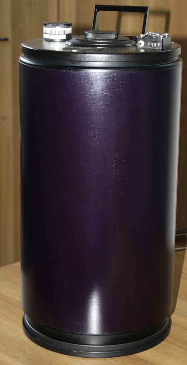
Above, the tube assembly ready to be mechanically and optically tested.
We’ve also provided the rings holding the tube to the mount. They were obtained from a thick section and then precision engineered. For weight reason the metal had to be very thin, so we put a 5 mm thick nylon band inside each ring to avoid any deformation. Once the rings have been assembled and before being anodized we tried to fit the original Losmandy type bar and the bar on which the customer would normally fix the guide telescope etc. Despite the original constructor being quite famous and the telescope rather expensive we noticed with regret that all the components used were made with absolute approximation. The hole centres do not correspond with those set with numeric control (sometimes the discrepancy is about 0.5 mm) nothing appears to be orthogonal and even the bare eye can see the rings are not straight. The upper bar seems even worse. Not only the holes are not orthogonal, but the threaded holes which have been drilled on it are not in line with 1 mm or more variation between each other. This piece couldn’t be used at all and had to be made from scratch; in the case of the Losmandy we tried to drill again knowing that, if worse came to worse, we could have replaced it with a modified one from NortheK.
We believe that is possible to judge a wholesaler/constructor from the small detail, as a matter of fact, they might have beautiful pictures in their websites but still struggle to drill the holes straight.
Above is the final result. Luckily we could use the original Losmandy bar but the upper one was so much out of axis that the couldn’t mend it and we had to make a new one (in the picture it still has to be anodized). We worked meticulously and all our holes fit perfectly and keep the ring orthogonal (the previous manufacturer tried to achieve that by re-drilling the holes, because they were obviously uneven).
Epilogue:
Good evening Massimo,
It is a very windy night, the seeing is worse than horrible, the stars are twinkling and everything is twitching. However l’ve been able to take a few shots, just 5 images of 30 sec each in simple JPEG format at 1600 ISO, they have been done WITHOUT GUIDE and composed with Maxim DL. My first and quick impressions that it is fine: I tried to contrast the image and the eccentric, vignetting that I could see before has now disappeared (there is still a bit on the corners but it is symmetric) and the stars over the whole field are even, regular and punctiform. If you enlarge the picture you can notice that the star discs are slightly elongated but this is due to the strong wind and not to the telescope. Therefore, after a first visual inspection, I dare say that the problem has been solved in an excellent way. Congratulations!
I attach this awful picture so you can take all the measurements you want and as soon as I will have done something remarkable I will certainly send it to you.
Daniele
.jpg)
.jpg)
.jpg)
Above are the three enlargements (left, center, right). The deformation is symmetric due to strong turbulence and because the guide has not been used. The halo too is certainly due to the altitude winds. The image at the right hand side has been taken at the far edge (nearly cut) and therefore in a worse conditions than the one on the left and side.
.jpg)
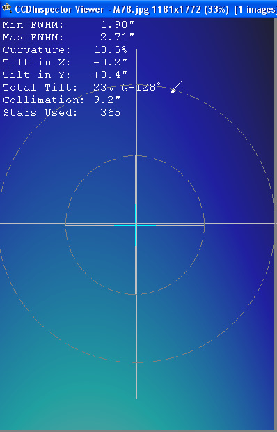
Please note that the CCD Inspector reports an insufficient number of stars to make the measurements. A wider star field should be considered to have a more reliable information.
In this kind of telescope a field nearly without curvature seems to confirm the hypothesis that the star number is indeed too limited to give a good image exploration, considering also that the lack of flatness of the image on the left. With more stars the situation should improve even more.
The second image is especially significant because it partly takes into consideration the collimation. We have now a field almost perfectly flat, with the right part to be improved with the collimation and it will certainly be done as soon as the improved seeing will allow it. As you can see, the difference is huge and once properly set this instrument will perform at a very high standard (high quality optics and mechanics used by an expert and reputed customer).
Whit this project we are proud of being able to satisfy an experienced amateur astronomer and to have upgraded a prestigious optical train to perform as per the original design. Beyon the monetary aspect, which should be left to personal judgment, retrofitting a prestigious instrument, like this Intes MK 200 f 6 with excellent optics but poor mechanics, has been a good investment for the owner and a big achievement for the NortheK Team!
.jpg)
A further adjustment has given much better results:
I’ve quickly collimated the “mak” and done four exposures at 800 ISO of 10 minutes each: I can state that there are all the makings of excellence, the star disc images have definitely improved and become clearer and smaller.
Daniele Cipollina