NortheK Cassegrain Classic 250 mm f 15 (second part) The manufacturer specifies that AxyS is built in different variants, sometimes at customer’s choice, and it is available with three or four spiders and anti-condensation system for the secondary mirror.
In the Cassegrain 250 mm f/15 was used the three spiders version as it was found to be the best suited for high-resolution applications, while the anti-condensation system was not installed since the glass is housed well inside the telescope and not affected by mist problems.
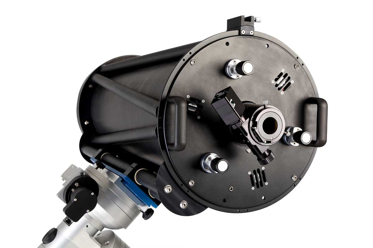
Accordingly, two fundamental elements of this optical tube assembly were examined: the primary mirror cell, fitted as standard on all instruments of this diameter; and the secondary mirror support, also this fitted as standard on all instruments of this diameter. It is worth dedicating a few words about the optical tube assembly of the Cassegrain 250 mm.
As can be seen from the image above, it is constructed with a carbon fiber truss system, marketed under the trade name of UnitorK 25, consisting of eight tubes held in position at the ends by ball joints mounted on alloy terminals, all suitably fixed on flattened bearing rings. A double end ring is indispensably used to support the spiders tensioners, so that no force will be able to deform the optical tube structure. In this way, the collimation is more accurate and immediate. The eight-tube carbon fiber truss system represents the lightest and strongest solution ever. There are no sign of torsion or bending of the structure, which is further reinforced by the dual rail (always in high modulus carbon) that supports the Losmandy bar connecting it to the frame. The dual rail tubes, always in high modulus carbon fiber, are additionally reinforced by having a thickness greater than those of the upper truss system. The tubes are produced by NortheK according to a proprietary design and are not derived from products available on the market.
The inner carbon tube cover is at customer’s choice, as it can be fitted or not. In fact, it has no structural purpose other than protecting the optics (in addition to a metal cap supplied as standard) and it can be easily slided out by removing the primary mirror cell. The manufacturer has not made ??use of any carbon honeycomb material due to its lesser structural strength and reduced thermal properties. Moreover, an optical tube made of honeycomb material poses some problems of residual stresses at the metal-composite interface, which solution is not very cheap. In contrast to other manufacturers, NortheK has chosen its own way, more rigorous and complex to optimize, but certainly more functional and innovative, even if more costly.
During the nearly two years of tests, the Cassegrain 250 mm has shown to be able to always and consistently work at the limit of its technical capabilities set by its diameter and focal ratio, with the only variable being that of the sky conditions (seeing and transparency); and this is not a minor detail. How many, even larger, telescopes – besides raising issues of transportability – remain unused for many evenings….. It is worth reminding that the instrument is highly-portable without any fears or worries and it can be easily carried around on the back seat of the car without even putting it back in its case as its sturdy construction is not at all affected by this kind of use.
In fact, a good a telescope can only be truly assessed when pushed to the limits of its possibilities, and constant photographic observations at f/30-40, as well as continuous star tests have confirmed the validity (and the optical quality) of the design.
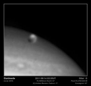
Very telling is this Ganymede obtained by resizing a wider field image. Even though taken with low average seeing, it does nonetheless show that the entire system works perfectly well and in the best possible manner even when the instrument is pushed to its limit. With a better seeing, also the result would obviously be better.
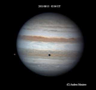
Here is a good quality picture obtained with low average seeing, when Jupiter was not in the best position to be photographed (Andrea Maniero – 13 Aug 2011).
Another fine picture taken by Andrea Maniero in August 2011.
In conclusion we can say that, even though this telescope is not for everybody’s pocket (the complete instrument used for the test costs about 8,200 Euros incl. VAT, which is perfectly in line with what is offered on the market), the NortheK Classic Cassegrain 250 mm boasts advanced technical solutions, all key characteristics for a definitive telescope that for many years will not make feel the need to be replaced if not for an instrument with a much larger aperture of at least 100 mm or more. The telescope can be obviously tailored to suit the customer’s requirements.
It is important to note that even for such small instruments the manufacturer has focused on the rigorous quality of the technical construction, while innovating where possible with the aim of offering a product that stands out from the more or less copied and repetitive offers available on the market.
Article published in an abridged form in “l’Astrofilo” magazine on December 2011 and shown here in its entirety.
A key issue in the design and construction of an instrument -with the aim of ensuring that the optics perform at their best- is that related to the thermals within the optical tube assembly.
We are obviously referring to the problems of achieving and maintaining the thermoregulation of vitreous masses and to the elimination of the column of hot air persisting in mechanical components.
in actual fact the problem is a bit more complex, and there would be the need to talk about the materials used to build the mechanics, of the temperature delta between external and internal environment (varying during the observing session), and of the vitreous mass -fundamental issue especially in sizeable diameters and thicknesses.
Consistent with the manufacturing costs, every producer try to address this matter in the simplest and functional way, as in fact, even though many amateur astronomers do not realize just how detrimental this problem can be, it is one of the key factors that can affect even good optical instruments.§
Some have explained in a very scientific and clear way in countless articles and essays the formation and behaviour of these thermals inside a telescope tube, and also provided valuable guidance on how to reduce this occurrence, at least in some optical designs and for certain diameters.
As for us, we have tried to follow certain design criteria, less strict in small diameters but much more sophisticated in optics with diameter greater than 300 mm, so as to reduce as much as possible the interference of this phenomenon with the performance of the optics being used. Reducing the disturbances caused by thermal inertia is neither simple nor inexpensive and, what’s more, it has to be taken into account already in the early design stage, thus avoiding having to later take apart and modify carefully assembled structures. As a continuation of this topic we will analyze the technical aspects of this problem, while leaving for the moment aside all general basic considerations that would be too tedious for readers.
Many amateur telescopes fail to perform adequately due to two main reasons:
scollimation;
non-thermal control inside the tube.
Given these two assumptions, we can safely forget for a while about the degree of correction of the optical surfaces, obstruction, etc. Solved these two issues, we shall then solve the nonetheless fundamental third one, namely keeping coincident the optical axes.
When we talk of thermals inside the telescope tube, readers are well aware of the problem, as they surely remember the “dancing” images that do not want to stay still or the heat plumes that affect all star tests, and not just those. There are plenty of ways to master the problem and diminish its devastating power on the wave-front, some are simple and cheap, others expensive and complicated, but who constructs an instrument, or buys it, and does not take it into account, it will inevitably achieve very poor results, regardless of the optics quality and price of the telescope.
As for all subjects, also in matters of instrumental technique there are some basic rules that, as mentioned, must be followed and which differentiate a toy from a technical instrument, even if for amateurial use. There is no need to enter into extremely lengthy and complex explanations, because whoever has the technical know-how to understand and apply them can easily find plenty of material in many specialized texts. However, we believe that providing some basic guidelines, helpful also for adopting the most simple measures and solutions, would be very useful to those who use and possess limited-size telescopes.
Fig. 1 – a collimation test of a mirror that has almost reached the correct thermal equilibrium.
First premise: no telescope and no optical layout is free from thermal problems (or air currents inside the tube, or temperature differentials between the glass and the external environment, or transfer of human body heat in proximity of the wave-front, or….).
Second premise: the thermal problem can in part be solved in technological terms, and in part in methodological terms. The first can cost a little or a lot, the second does not cost anything but it becomes the “high school entrance exam” for the amateur astronomer.
Having established the cornerstones of the argument, we can begin to develop a thought that readers can then easily expand on their own by further studying every single aspect on specialized texts, and perhaps conduct some experiments on their own telescope -good or bad as it might be. While in two previous articles we talked in a very general and informative way about the optical tube of reflector telescopes, we now try to further explore some issues -thermoregulation in this case- part of the set of basic rules for constructing or buying a telescope. The market offers everything at whatever price, and at any price it also offers equipment built without a precise technical scope, if not that of maximizing the profit for the manufacturer.
The first matter to consider is not that relating to the telescope mechanics, but rather the optics. It is not difficult to realize that in the case of a 50 mm thick mirror compared to one half that thickness, we shall have rather different thermal behaviours, just as an achromatic doublet will stabilize much faster than a triplet or any other arrangement fitted with corrector, ….without forgetting the eyepieces that should not be kept in the pocket. For now we shall focus on reflecting systems, since for the refracting ones there is little room for intervention and only the most conscientious manufacturers (not necessarily the most renowned) implement mechanics that take into account this aspect, always assuming that they have the necessary know-how for doing it.
Let us take, for example, a reflector telescope with a diameter of 250 mm, whose focal length and optical layout do not interest us here. With standard optics we will have a glass about 50 mm thick and an approximate weight of 4.5 kg, while with a 23 mm thick glass we will have a weight of about 2.4 kg. From this we can begin to understand the difference of the vitreous masses at stake. But why then use 50 mm mirrors? Very simple: they are easier to work with and the mechanics can be kept very simple as they do not tend to deform; the downside is that they weigh more and are almost never in thermal equilibrium -to say nothing of the optical parameters set by the manufacturer. Why not everybody use 23 mm optics? Obviously because if an optic of this type is not assembled with high mechanical precision, it will cause serious deformation of the geometric figure. It is a balancing act that only the manufacturer can resolve and that only the customer can decide to accept or not.
Fig. 2 – a mirror cell from the ’70s. The task of supporting the 46 mm thick glass disk was assigned to three triangles of carpet. The thermal inertia was, in this case, completely uncontrollable
Bringing the mirror to reach a good thermal equilibrium does not exempt us from keeping in mind all other issues that we mentioned, namely, the mechanical components that should allow fine collimation, the absence of torsion and bending, keeping coincident the optical axes etc. Now that all aspects and factors to consider have been identified, the matter becomes a bit more complicated.
Fig. 3 – a Ronchigram disturbed by the heat of a hand placed in front of the mirror. On the optical bench for big size mirrors (from 400 mm and above) even the heat from a human body 3-4 metres away can give rise to deformations wrongly attributed to configuration errors.
What factors can determine an inconsistent evolution of the temperature within and in our optical tube? Undoubtedly the outside temperature (varying during the observing session and dictated by the observing location and, in some cases, by the proximity of the observer), the tube mechanical structure in the broad sense (i.e. materials, internal dynamic flows etc.), the glass and finally the optical layout, which must not always be left for last since a meniscus system often prevail over other factors. In our construction plan, or instrumental choice, we could therefore draw up a checklist of all these factors and gradually cross out those that do not represent a problem and just leave the ones that are a problem. It is not down to the user to conduct in-depth studies on the behaviour of materials in a telescope, but rather to the manufacturer, who must be able to substantiate in very simple and plain words each design choice, whose criterion can sometimes be just the cost, except that the user must know this in advance.
The first aspect, and also the easiest and fairly straightforward to reason out, relates to the thickness of the glass; straightforward because it will be sufficient to ask our optics supplier to stay on the “thin” side if he can, and if can’t, we will have to fall back on alternative thermal correction systems. From this thickness shall then depend also the mechanical construction. Please note that since this magazine is addressed to a wide readership and is not a specialist text, the explanations and descriptions have been kept basic and limited; we apologize to all those whose skills and knowledge go far beyond what can be summarized here. Let us now return to our 250 mm mirror of Pyrex glass (today no longer produced; Schott now offers in its place Supremax 33, which is rather costly but has similar characteristics). To make the concept easy and quick to understand, we used a free program called “TelescopeMirror Cooling Calculator” downloadable from https://www.cruxis.com/scope/mirrorcooling.htm, which we recommend our readers to play with as it allows to compute different types of glass with varying thicknesses.
As a first experiment we shall just play with the glass thickness -please note that so as not to generate confusion and allow everyone to repeat it (because it is nice to see it in action) we have not changed any of the program default parameters.
50 mm thick glass:
fig. 4 – 50 mm Pyrex mirror
Let us observe this graph: after 120 minutes in default mode the temperature profile of our mirror has NOT yet reached the 10 degrees C target that we have set ourselves, but rather, it is a good one and a half degrees above it (the standard calls for 0.5 degrees C maximum temperature delta, but that is always difficult to achieve and maintain).
fig. 5 – 50 mm Pyrex mirror: temperature evolution
Let us now look at this further computation. We can see that we have started from 20 degrees C and after 120 minutes we have reached about 11.5 degrees, but let us carefully observe the red line which is the one that represents the “heart” of our glass disk. Only towards the end of the curve it gets near to the other two, and in any case the temperature delta is still quite high. Under these conditions, how important do you think it is the optical correction of your mirror? Observe also, always in Fig. 4, that the red line is slightly bowed and discover the reason why.
fig. 6 – 25 mm Pyrex mirror
In this graph, to be compared with that in Fig. 4, we have kept the same parameters while reducing the glass thickness to 25 mm. We can see that after 120 minutes we have reached our target temperature of 10 degrees C and the red line is perfectly flat.
fig. 7 – 25 mm Pyrex mirror : temperature evolution
Also in this case we can see the perfect correspondence of the three lines with a close proximity between them and a rapid descent to the desired value. The problem of the “heart” of the glass disk is practically non-existent and theoretical stability has been practically achieved.
At the end of this first simple experiment we have only shown what was logical to think, but most importantly, we have shown that, with regard to the glass disk itself, its thickness is of fundamental importance and a key factor directly affecting our telescope’s performance and efficiency. Start the program that we have indicated above and try changing glasses and thicknesses, then compare the various graphs. This process is definitely very interesting for understanding how this issue really counts, but the reasoning needs to be further developed with all complementary aspects since here it only tells us how a glass disk behaves in certain situations (change also the temperature to be maintained by taking, for example, from 20 degrees C to 15 or 13 degrees like in a garage and then take look at it).
We have explored some elements of consideration on the behaviour of glass disks according to their own temperature and ambient temperature, which as a reflection it is also the behaviour of the wave-front mirrored by our optics. Without wishing to overload our explanatory journey, it is interesting to consider that a further “passive” factor -i.e. not dependent on external thermoregulation aspects- in addition to the thickness of the glass is that related to the type of glass. While for refracting lenses there is very little that can be done since the glass is chosen according to the functioning requirements and final optical performance, for reflecting mirrors is a different matter. Each type of glass for mirrors has a well-defined behaviour, specific technical features identified during design and production, and levels of performance in relation to the environment in which it operates. That said, remains outstanding the matter of the price, which is a sore point for amateur astronomers, although much less than it is generally thought to be. Would you like an example?
As can be seen from the program and graphs used above, we are been asked the type of glass on which to apply the formulas for calculating the acclimatization times. Remember that with just a few Euros it is very often possible to automatically obtain better results. In the following table we use a symbolic example of what we mean, and show how industrial choices are sometimes guided by harsh economies of scale that perhaps do not meet the needs of more attentive users.
Table 1 – type of glass, characteristics, costs (Courtesy Oldham Optical)
Glass Type
Thermal Coeff of Expansion (PPM/Deg C)
Thermal Conductivity (W/M/Deg C)
Cost
Plate glass
> 8.6
0.75
1
Common window glass
Suprax
4.3
1.2
1.1
Excellent price/performance ratio
Pyrex
3.25
1.13
1.3
Very close to Suprax,production suspended
BK7
7.1
1.11
1.1
Note the strong thermal expansion
BVC
2.4 – 2.8
?
1.2
Ideal for large mirror
Supremax 33
3.25
1.2
2.5
The alternative to Pyrex at nearly double the cost
Zerodur
> 0.02
1.64
>10
For those who can afford it…..
ULE
> 0.05
1.31
…..
Zerodur’s rival
Borofloat
3.25
1.11
…..
Another alternative to Pyrex
E6
2.8
1.1
…..
Ohara’s Pyrex
All trademarks are the property of their respective owners. We kept the above table as simple as possible to make it easier to examine ??the thermal expansion values and indicative price, and from these two columns draw the appropriate conclusions. We have omitted some optical glasses produced in Russia and the high-performance (and consequently pricey) Clearceram-Z (Ohara), and others that are clones of the glasses shown. The higher the thermal expansion value, and the more the glass is prone to mechanical deformations of its geometry, due to the varying temperature.
We can therefore deduce that, for example, the use of BK7 glasses in mirrors is a financial nonsense seen that on the heat front it performs very poorly, compared to Suprax that has a very similar cost and a thermal expansion value that is little more than half. Also the lucky owners of mirrors in Zerodur or ULE must however thermally control their telescope, even if in a less dramatic way than all the others.
Let us close the part relating to glasses by pointing out that on the web it is possible to find many publications showing how the optical correction of a mirror is practically destroyed unless it is thermally stabilized. It is worth pondering on this before asking for certificates with astonishing correction values.
Our telescope must therefore reach in the least possible time two precise thermal conditions:
the glass disk or disks must reach a uniform temperature of the entire mass equal to that of the operating environment;
the glass disk or the disks must follow the evolution of the ambient temperature during the observing session.
What if this does not happen? Well the answer is simple because we will have very significant deformations on the wave-front (more than you can imagine), with a corresponding destruction, or increasingly significant degradation of the image as the thermal deltas progressively widen. In a short-focal length telescope, dedicated perhaps to wide-field photography, this effect is less noticeable while it is greatly felt that relating to the focus variation during exposure, whereas in a telescope dedicated to high resolution (i.e. Moon, planets etc.) this is one of the DETERMINANT factors for achieving interesting results without having then to go over them with super processing techniques that we prefer to call artefacts.
Fig. 8 – in this image of the Mirror Lab we can see the laying of the ceramic hollow cores on which the molten glass will be poured.
After the glass blank has cooled, the cores will be removed and the voids left will greatly diminish the weight of the glass disk, resulting in reduced thicknesses and thermal adaptation times. In this specific case it was borosilicate E6 made by Ohara. In the NTT-ESO telescope it has also been experimented the technique of blowing forced cold air inside the rear cells, in order to accelerate the reaching of the optimal thermal curve -a forced ventilation system built inside the glass disk.
If we have chosen, in accordance with everyone’s financial means, a reasonably performing glass, such as Suprax, for telescopes up to 300 mm, with limited thicknesses and weights, or Supremax 33 (or similar, obviously) for greater diameters and thicknesses, the only thing then left to do is to start looking at the optical tube structure. For the more lucky ones the problem is obviously less severe as there is always ceramic glass, ULE, and the like. For intellectual honesty, it must be said that manufacturers of high-level optics consider that up to certain diameters a glass with similar performance to Pyrex is more than sufficient for the needs of any amateur and even professional user. Read, for example. the fine monographs of Robert Royce on this subject and published on his site, or those of Oldham Optical, a bit more concise but very “pragmatic”.
What can be done so that, while preparing for an observation evening, our optical tube reaches thermal equilibrium, so as to be able to check the collimation and begin the observing session?
First, those who have a fixed location know very well that they must open their observatory a few hours before, switch on the forced ventilation systems etc., but for all others who keep their telescope inside the house a great method to follow is to NOT keep it in the house, if possible. Put it in the garage where the difference between the inside and outside temperature is minor; this will save you a lot of time as the degrees needed to make up for the difference are less. A second recommendation is to place the telescope in the garden at least a couple of hours before using it (before dinner, for example), switch on the cooling systems that every conscientious manufacturer should have installed, and leave them to do their job. The results will be varying from telescope to telescope. Obviously a closed tube of a catadioptric system will take some time to acclimatize and in any case it will NOT follow the temperature curve of the observation sites; this also due to the type of mechanics used.
We strongly not recommend a meniscus system, often perhaps 15-20 mm, to anyone who does not have a fixed location and mechanics that take seriously into account these issues. A Newton telescope with a closed tube (understood as a monolithic tube) is very easy to bring to thermal equilibrium -especially if it has a good truss structure design- in the same way as all open systems. Please note that this does not exempt from having available the forced ventilation system which is still indispensable.
The arrangement shown in Fig. 9 (fitted to a photographic instrument) is somewhat significant of what is intended. It must be noted that even though the glass is exposed to the atmosphere, the system is nevertheless equipped with forced ventilation, in order to bring the mirror (25 mm thick) to the required thermal equilibrium as quickly as possible.
Fig. 10 – A professional 600 mm aperture telescope with Zeiss optic.
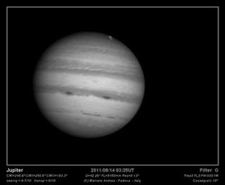 Another fine picture taken by Andrea Maniero in August 2011.
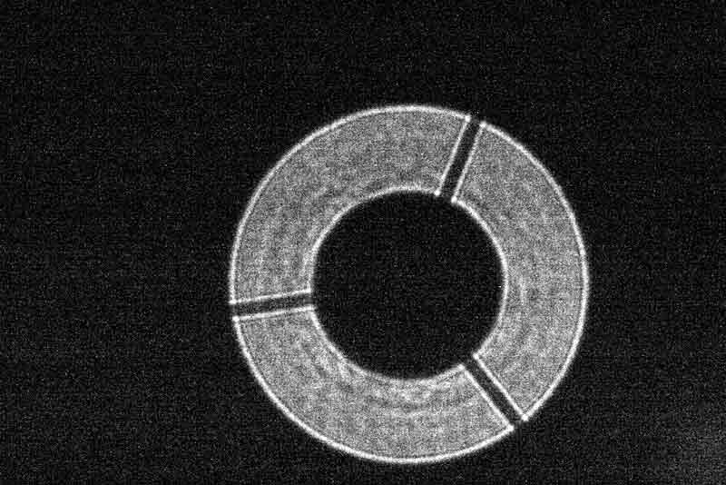
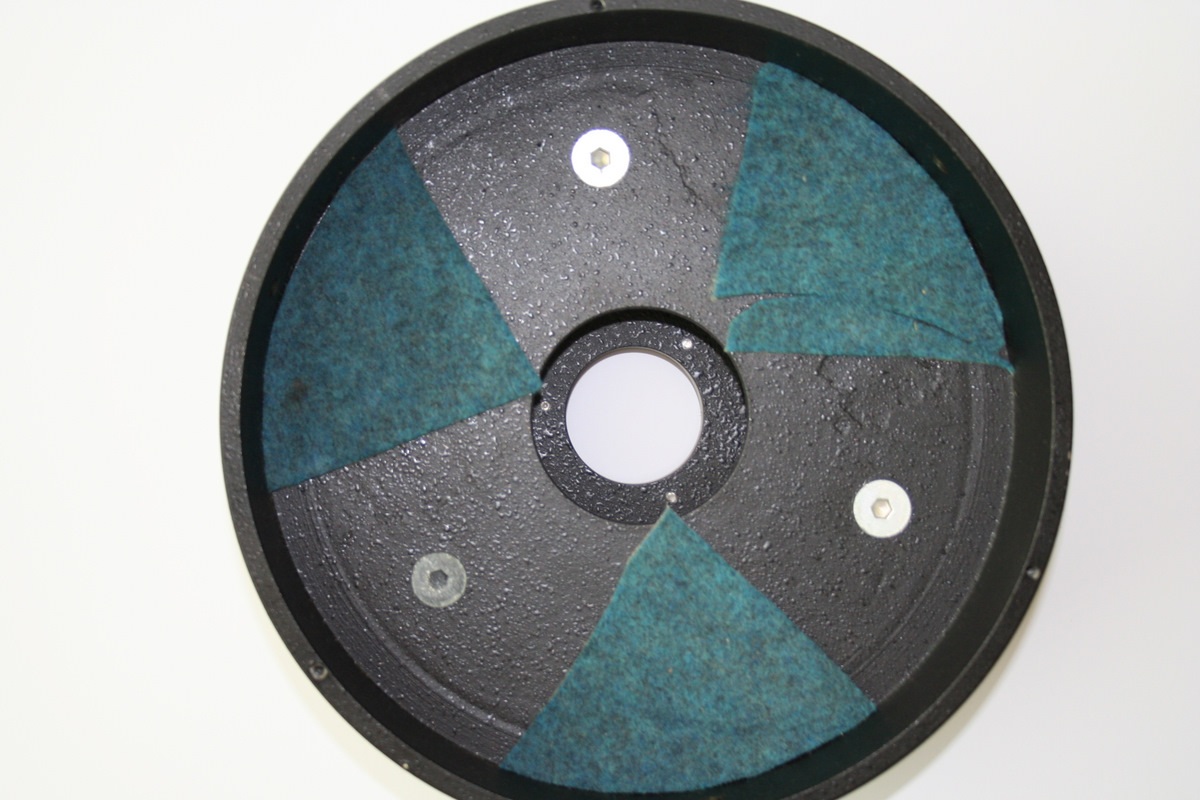 Fig. 2 – a mirror cell from the ’70s. The task of supporting the 46 mm thick glass disk was assigned to three triangles of carpet. The thermal inertia was, in this case, completely uncontrollable
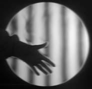
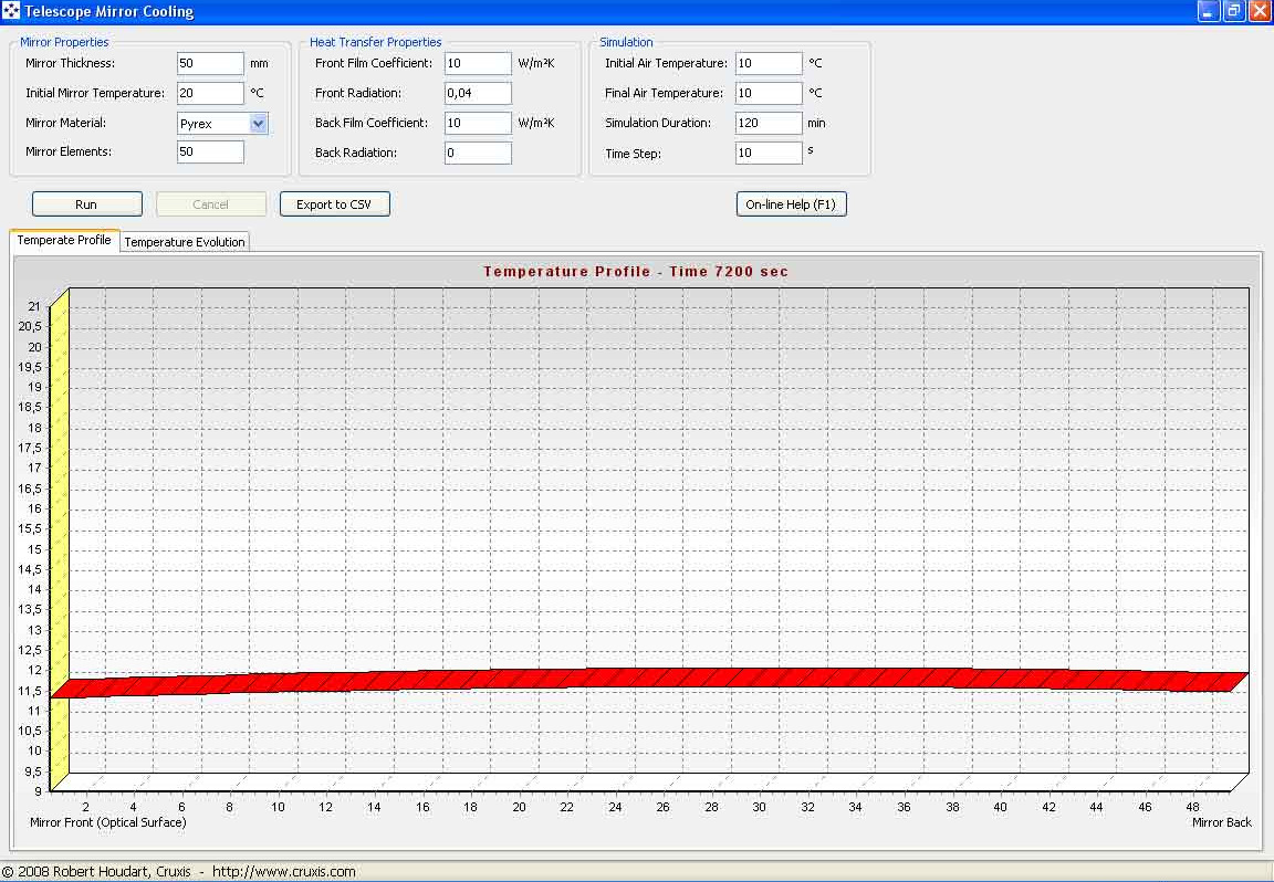
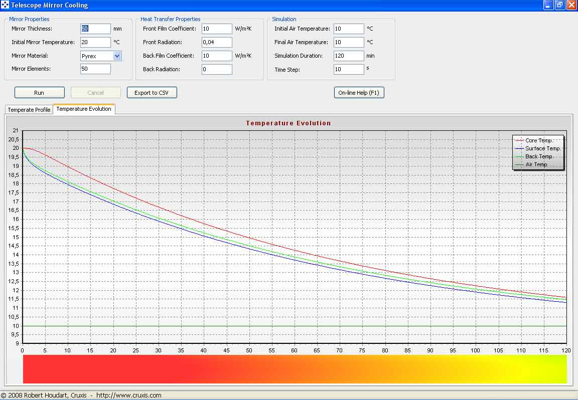
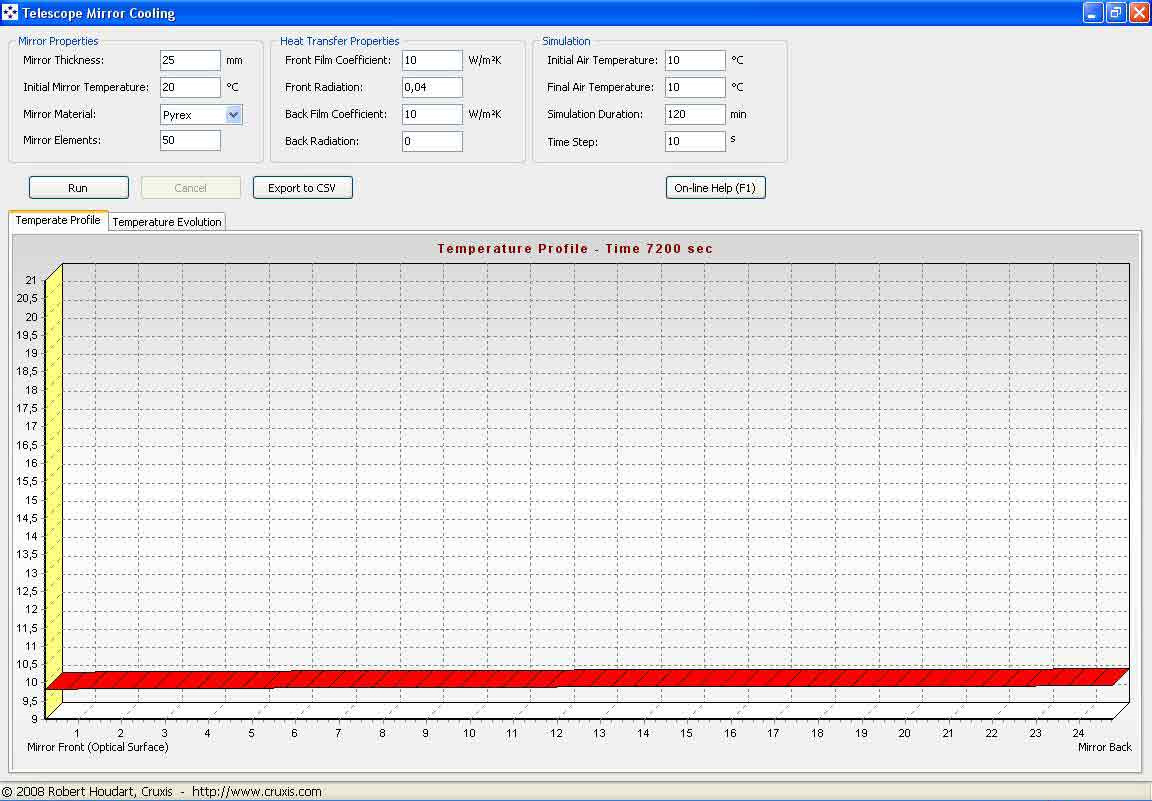
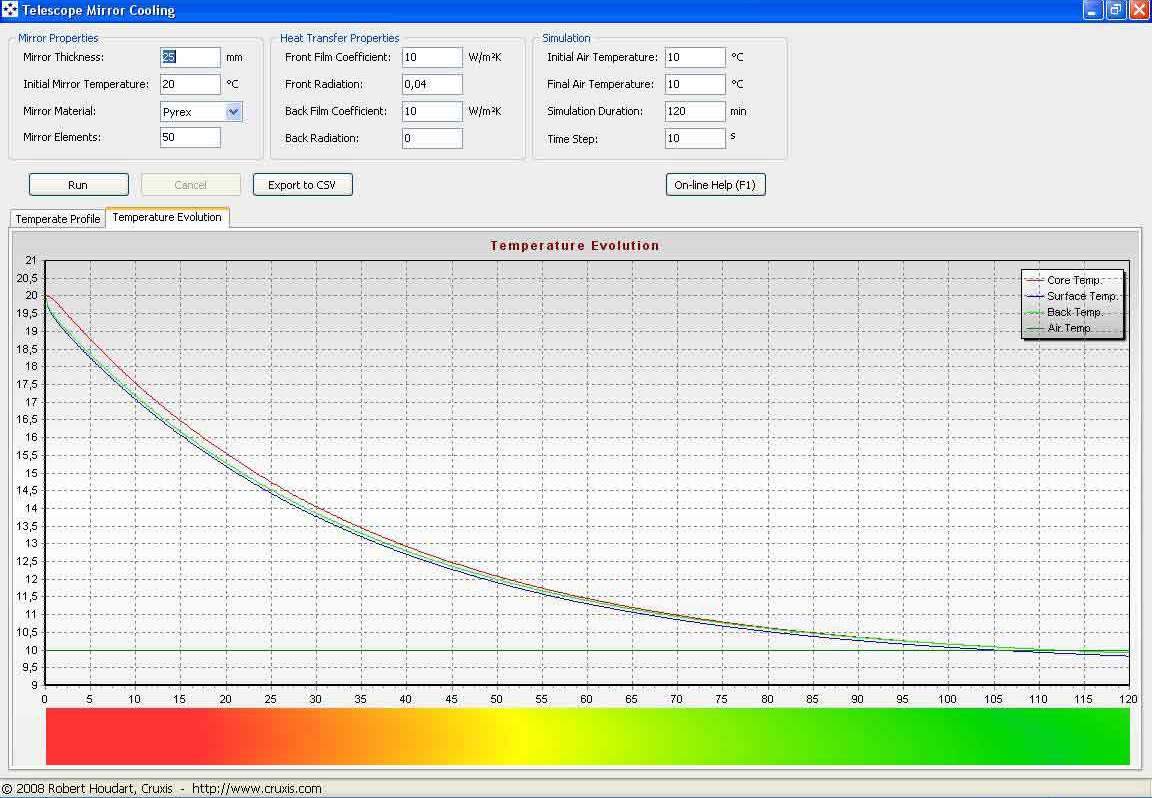
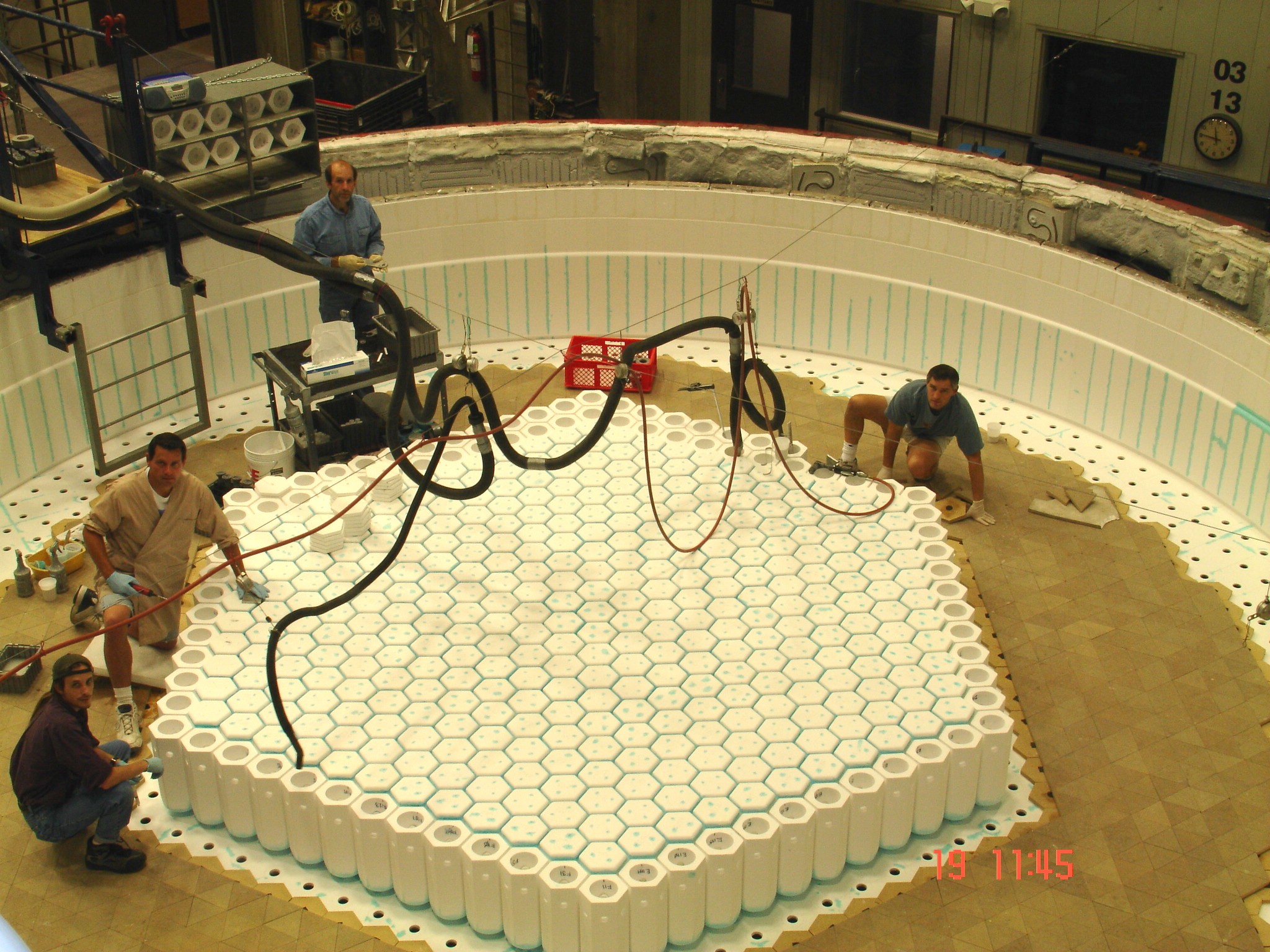
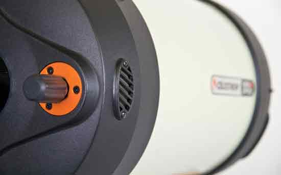
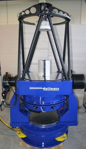 Fig. 10 – A professional 600 mm aperture telescope with Zeiss optic.