StabilobloK 35 is the most advanced cell for 350 mm reflector telescopes, ideal with thin glass (35 mm) and suitable for any optical scheme.
Thanks to some highly technical improvements, this design represents the technological evolution of the StabilobloK 25 and this cell can be considered the finest for the amateur market. With this cell the amateur astronomer can totally avoid the problem of optics under-performing because of poor support stability.
.jpg)
The StabilobloK 35, as well as its smaller version (25 series), is designed to remove almost completely any mechanical element of disturbance from the optical structure of the telescope.
With a 350 mm diameter the weight of the glass is quite heavy therefore it is important to arrange its position carefully and, most of all, to make sure that it stays in place throughout the observation. For this reason the StabilobloK 35 has got a very robust mechanical structure also designed to prevent any element which could possibly introduce errors in the mirrors system.
.jpg)
.jpg)
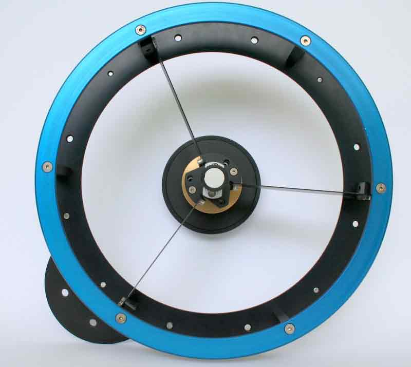
The cell works with 18 floating points designed and made for the purpose. There are no laser or water cut parts, everything has been precision engineered from solid alloy. The design of the cell is the same as the 25 series but loads and tolerances have been adapted accordingly.
The cell has got anti-mirrorshift and anti-mirrorflop systems with a NortheK self-centering function which allows all the elements in contact with the light cone to be kept on axis. It is suitable for focuses from 2,5″.
There are 6 very strong side supports, made with a special structure which can absorb deformations on the contact points and keep the system in balance whenever the edges are not parallel.
.jpg)
.jpg)
The position of the 18 floating points has been designed to minimize the deformation of the optical surface. It is easy to determine the value of these deformations with a simple calculation program. Every vertex of each triangle can work under 50 gr pressure; they are singularly tested on the bench and made operative 35 gr pressure. Thus the system is very reactive. Each joint (BWK2 system) is put under stress for several hours in order to improve the performance keeping the mechanical values unchanged. You will not fin any other mass produced product for the amateur market with the same mechanical accuracy and cost.
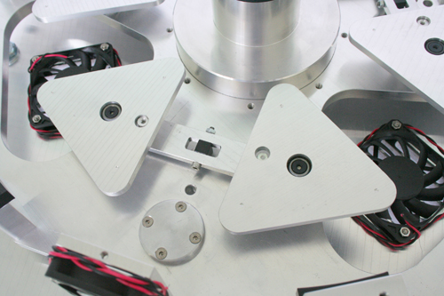
The element of innovation StabilobloK 35 cell is a special system for the removal of the boundary layer from the mirror surface. This important result is achieved with the use of 3 extracting fans positioned by the mirror and 3 additional fans at the rear of the cell also assisting in the removal of the layer and the air column. Another option available is the electronic control of the extracting system (along both the radius and the axis) which we strongly recommend to anyone pursuing the best performance in high resolution.
The setting of the optical plane is done on the production line so that when the product is delivered it is ready for the star test.
.jpg)
.jpg)
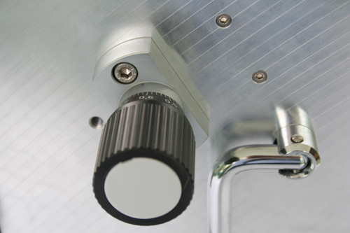
Every StabilobloK cell has got three stainless steel and aluminium shifting systems, larger than the 25 series and with a 0,02 mm accuracy, each with a internal reducer. The activation pivots are made of ground steel and they slide inside self-lubrificating matrix technopolymer systems designed to work in all environments. The end joints are more advanced than those of the smaller cells. In fact they are made with high precision bearings in sintered steel and bronze, spring loaded in order to avoid any side movement towards the optical plan. Obviously the springs do not interfere in the flatness of the cell’s plates.
The cells can be personalized upon the customer’s request.
| Characteristics | Technical specifications | |
| NortheK | StabilobloK | ST 35 |
| Alloy | Halo 25 | |
| Metallic composition ISO | AlMg4,5n0,7 | |
| Chemical composition | Si,Mn,Fe,CuTi,Mg,Cr,Zn | |
| Density (gr/cm3) | 2,66 | |
| Coeff.of Thermal Expansion (10-6 k) | 24,2 | |
| Degree of roughness | N6 | |
| Thickness mm | +-/0,05 | |
| Parallelism mm | < 0,1 | |
| Planarity mm | < 0,2 | |
| Shape stability | Optimal | |
| Protective anodization | Optimal | |
| Surface protection | Black anodization | |
| Nuts and bolts | Stainless steel | |
| Mirror support system | 18 floating point supported by ball joints made of steel and bronze composite | |
| Lateral supports | 6 points | |
| Optical plan adjustment | Adjustment system in chrome rectified steel | 3 points of fine adjustment (0,02 mm) per 120° |
| Vibrating damping system | ||
| Forced ventilation | 3 axial extraction fans, 3 radial extraction fans | |
| Customized for different tube | Upon request | |
| Weight without optic | kg. 10 |
Specifications may change without notice
| Product code: ST 35 | Sale unit: piece |
Can StabilobloK evolve?
The design of this component has been conceived to allow further updates and improvements.
We would like to remind you that every IMPORTANT technological improvement brings a very high cost increase.
The StabilobloK project can be upgraded not only from an aestethical point of view, it is also possible to improve the performance of both, its structure and accessories.
For instruments with fixed position and diameters between 500 and 800 mm. it is possible to use more appropriate metallic alloys or specially made steels. The plans adjustment is made with an electronically controlled system the construction tolerances can be dropped down to 0.01 mm. and the thermal expansion can be better controlled with an accurate material selection.
The system for the thermostation of the glass is also more sophisticated, as it incorporates thermometric sensors, automatically controlled systems and refrigerating fluxes.
The lateral supporting systems are self-compensating, while the lower supporting points have an adjustable compensator (alternatively we can offer a more advanced solution with an electromechanical system PC controlled). In the AxyS A2 version the adjustment of the primary’s plan can be made with linear system; in this way iy is possible to re-set the back focus as many times as you want and save all the different positions in the memory. You could modify the field of full light and the necessary extraction in accordance with the characteristics of the shooting sensor and the optical train applied along the back focus. Thermometric sensors and surface refrigerating systems provide all the information to the PC which will optimize all the configurations.
The position of the secondary mirror, that is to say its distance from the primary, is electronically controlled and can be adjusted from the PC.
The primary and secondary baffles are machined with special instruments from a solid bar in order to locate the necessary diaphragms with the highest precision.
For this kind of cells we can also provide special customized focus and 4″ and 5″ diameter, they are made in steel, Ergal and Titanium, motorized and PC controlled.
We do not have a catalogue for those products as we manufacture them on customer’s request and modify them in

.jpg)
.jpg)
.jpg)